Tables and Parts Lists (Tutorial)
|
|
Tables and Parts Lists (Tutorial) |
www.CAD6.com |
|
This chapter uses some commands that are only available in CAD6studio and/or CAD6industrie!
AimThis example should explain how to generate parts lists and tables. You will get to know the various methods of making multiple copies and how to align text into predetermined areas. In addition it goes into the process of exporting graphics for use in other applications (e.g. word processors). The example is the table which you already know from the introduction to the chapter on the pen and layer concept. Generating parts lists and text boxes for technical drawings follows a similar procedure.
SettingsTutorial.mkd
BasicsThe procedure for producing a table is determined by the type of table. Parts lists for technical drawings make use of a predetermined grid, tables in technical documentation usually cannot exceed certain dimensions. This example has an inner frame measurement of 140 × 70 mm. This is a precondition.
Begin with the pen "0.25 mm\Solid Line Narrow" and use Draw > Polygon > Rectangle to draw a rectangle 140×70 mm. Use Trim > Trim Object > Resolve Completely to split the rectangle into individual lines.
Choose Modify > Move / Copy Objects > Multiple Copy, Object Division. This makes it possible to copy a specified object to the outline of another object. In the example, seven equally spaced horizontal lines are to be added. This means that the top horizontal line is to be copied seven times in the vertical distance. Identify the top line, and with "Corner/Endpoint" snapping mode on, place a reference point at the start point of the top horizontal line. Identify the vertical line as a reference object. Choose "linear" in the dialog and enter seven as the value. Close the dialog with OK. Seven horizontal fields should appear on the page (Figure 1).
Figure 1
The process used means that there are eight copies of the original object in the specified area. This also means that copies are placed at the start and end points of the specified reference object. However, there are already lines there (the top and bottom edges of the rectangle). To avoid being continually asked by the application which line you wish to use (e.g. during identification), remove one of the lines from the top and bottom using Modify > Delete Objects or by using the DEL key. Identify one of the top lines and answer "OK" to the application's "Choose Objects" question. Repeat the process for the bottom line.
To generate the vertical lines on the right hand side, use Modify > Move / Copy Objects > Multiple Copy, Line Division. Identify the right hand line and specify the corner point A (with "Corner/Endpoint" snapping mode active) as the reference point. The start point also lies at point A and the end point is the midpoint M (specified with "Midpoint" snapping mode active) of the upper horizontal line. Five sections should be created (six lines); once again, there are two lines on top of each other at the left, one of which has to be deleted (Figure 2).
Figure 2
To shorten the column dividing lines in the top section to 2mm, add a Construction Aid endless line whose intersections with the vertical lines will be used later as trim points. Choose Construct > Construction Aid Endless Line > Parallel, numerical and enter a distance of 2 mm. Identify the second horizontal line from the top and place the Construction Aid endless line above it (Figure 3).
Figure 3
Use Trim > Trim Object > Length / Radius to Object you can shorten the middle four vertical lines to the Construction Aid endless line. Identify the upper part of each line and then click on the Construction Aid endless line. Repeat this for each of the four lines (Figure 4).
Figure 4
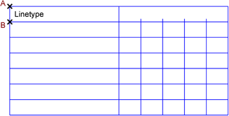
The basic structure of the table has now been set out. Next, put a line of text into the upper left cell. Use Annotate > Text > Standard and enter Line Type. The text should be left-aligned and 5 mm high (in the example, the Arial TrueType font is used). Close the dialog by clicking on OK and position the text the desired distance from the left edge. To align the text vertically, choose Modify > Align Objects > Centered, Frame Vvertical. Identify the text and (with "Corner/ Endpoint" and "Midpoint" snapping modes active) click on the top right and bottom right corners of the box surrounding the text (see Figure 5)
Figure 5
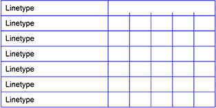
This text can be used as a template and be copied into all the relevant cells using Modify > Move / Copy Objects > Multiple Copy, Offset. Identify the existing piece of text and choose the upper left corner of the field as the reference point. The start point also lies at the top left corner (A) and the finishing point lies at the field's lower right corner (B). Choose six linear steps and click on OK (Figure 6).
Figure 6
Use Annotate > Text > Standard and enter Line Width / Line Groups. Set the text alignment to "Centered", the text size to 4 mm and the text style to bold italic. Position the text in the space meant for it and use Modify > Align Objects > Centered, Frame Both to center it in the frame. Use the intersection of the Construction Aid endless line with the right hand vertical line as the lower right corner of the frame (Figure 7).
Figure 7
Use the same method to place the figure 0, centered in the top left number field. It should be 5 mm high and use the standard font. Copy this text into all the other number fields. Choose Modify > Move / Copy Objects > Multiple Copy, Array and identify the text object. The reference point is the upper left of the field (A). This point is also the first corner point. Corner point 2 is at the top left corner of the bottom left number field (B) and corner point 3 at the upper left corner point of the bottom right number field (C). In the first dialog box enter 5 for the number of linear segments (six copies) and in the second dialog box enter 4 (five copies) for the number of horizontal segments. See Figure 8.
Figure 8
You can now use Modify > Edit > Text / Attribute to alter each piece of text to the correct value. Identify and alter each piece of text separately (see Figure 9).
Figure 9
Alter the properties of the Line Types piece of text. Do this with Modify > Object Properties > Edit. After identifying the text, click on the "Special" button and alter the text style to "Bold Italic".
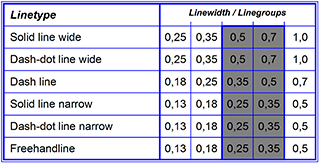
Finally, the tables appearance is improved by adding differing line widths and shading. Choose the pen "0.5 mm\Solid Line Wide" and (with "Corner/Endpoint" snapping mode active) draw the outer frame. Change back to the pen "0.25 mm\Solid Line Narrow" and use Draw > Line > Equidistant to draw a thin line 0.7 mm outside the last-drawn rectangle. To do this, identify the rectangle and click outside the surface. The corners should not be rounded (Figure 10).
Figure 10
The dividing line in the middle of the table can be given the properties of the pen "0.5 mm\Solid Line Wide" using Modify > Object Properties > Edit. To do this the relevant entry from the list in the dialog is chosen and enable the "Fix" check box.
To draw attention to the 0.5 and 0.7 line groups, a gray grid is placed behind them. Choose the pen "0.5 mm\Solid Line Wide" and draw a rectangle around the area to be shaded gray. Use the snapping function. Using Modify > Object Properties > Edit, set the rectangle's filling style to "Filling & Outline", click on the "Color" field and choose gray (or any other color) for the background (Figure 11).
Figure 11
Because the rectangle was drawn last, it is on top of the other elements in the table. Use Modify > Change Order > To Back to place the rectangle in the background (Figure 12).
Figure 12
ExportClipboardThere are various ways to make this graphic available for use in other applications. The usual way is to copy it to Windows' Clipboard using Edit > Copy. It can now be pasted into any application which uses vector graphics.
EMFYou can copy objects to an enhanced metafile using File > Export Objects > Enhanced Metafile. The current output properties are used. Most 32bit Windows applications which work with vector data can read EMFs.
To import an enhanced metafile into Malz++Kassner CAD6, use the File > Import > Enhanced Metafile command.
If you have the choice to use either EMF or WMF, you should always prefer EMF files. They use 32bit coordinates, complex surface descriptions including Bézier curves, nested outlines and further high-level structures that result in high-resolution, device-independent data.
WMFAlternatively, you can copy objects to a windows metafile using File > Export Objects > Windows Metafile. The current output properties are used. Most 16bit Windows applications which work with vector data can read WMFs.
To import a windows metafile into Malz++Kassner CAD6, use the File > Import > Windows Metafile command.
BitmapA further possibility is export to bitmap files. These can be read by many applications which handle bitmap graphics. Choose File > Export Objects > Bitmap to export to a bitmap.
To import a bitmap into Malz++Kassner CAD6, use the File > Import > Bitmap command.
SettingsIt is also possible to export parts of the drawing such as Construction Aid endless lines, markings and grids. This can be useful, for example, in technical documentation. Many of the graphics used in this tutorial were one with Malz++Kassner CAD6 and exported using suitable extra output parameters (markings and Construction Aid endless lines). The output parameters are set in a dialog called with Manage > Drawing Settings > Output. These settings can also be altered at the last minute by clicking on the "Options" button in the dialog of File > Print > Drawing.
In order to export parts of the current drawings to a Malz++Kassner CAD6 file, choose the File > Export Objects > Malz++Kassner CAD6 (*.mkd) command.
If the application to which you wish to export Malz++Kassner CAD6 graphics cannot handle TrueType fonts, enable the "TrueType As Surface" check box in the output parameters dialog. This setting converts all characters into surfaces before output to the Clipboard, a WMF or the printer. This procedure can also be useful if TrueType fonts do not print correctly on your printer.
|
CAD6studio Release 2026.0 - Copyright 2026 Malz++Kassner® GmbH