Parallel Outline (Equidistant) (Draw Menu)
|
|
Parallel Outline (Equidistant) (Draw Menu) |
www.CAD6.com |
|
This command generates a parallel outline (equidistant) relative to a specified object. A parallel outline is a outline which, with respect to all its points, has the same distance (offset) to the reference object. In the simplest case this is a line parallel to another line or a circle concentric with another circle.
After choosing the command, a dialog appears into which the distance can be entered.
The distance must be practical. For example, you cannot draw a parallel outline larger than 10 mm within a circle with a radius of 10 mm. In this command's parameters, you can choose whether the result shall be automatically simplified, and set the corresponding tolerances (see Curve / Surface > Simplify).
Any object consisting of "normal" elements can be identified as a reference object. These are lines, circles and circle parts, ellipses and ellipse arcs as well as all objects consisting of these elements. The objects are always treated as a whole. Some elements, for example text, dimensions and instances, cannot be used.
The identified object is referred to as the "reference object".
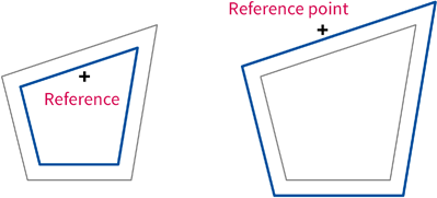
After identifying the reference object a point is entered which determines on which side of the reference object the parallel outline should be drawn (see graphic).
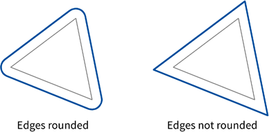
Based on parameters, the corners of the parallel outline will be rounded or not (see graphic).
Because of the definition (the same distance with respect to all points) of parallel outlines, all corners must theoretically be rounded. In many cases this is not required, and therefore this procedure is provided. There are also situations in which only one of the two options ("rounded" or "not rounded") functions. This often the case when there are pointed transitions between lines and circle arcs.
Parallel outlines are stored internally in different forms, according to the reference object's type. Lines create lines, circles create circles. All other object types create curves (open outlines) or surfaces (closed outlines).
The object is allocated to the current layer. It also contains a reference to the current pen.
If a parallel outline relative to a surface containing Bézier curves is created, there may be (extreme) inaccuracies. During the calculation of the parallel outline, the Bézier curve is treated as a polyline with three sections (Start point - Pivot point 1 - Pivot point 2 - End point). If the Bézier curve is relatively short and flat, this simplification is not usually very effective.
This command does not work with text in either Malz++Kassner CAD6's own format or TrueType-format. To draw a parallel outline relative to a text, the text first must be converted to curves or surfaces using the command Text > Resolve. Afterwards, parallel outlines can then be created (see graphic).
The problem with Bézier curves described above doe not arise with TrueType fonts as the Bézier curves in TrueType fonts are relatively short and flat. However, rounded corners should always be used in order to make the result look smoother.
|
CAD6studio Release 2026.0 - Copyright 2026 Malz++Kassner® GmbH