Gear Housing (Tutorial)
|
|
Gear Housing (Tutorial) |
www.CAD6.com |
|
This chapter uses some commands that are only available in CAD6studio and/or CAD6industrie!
AimDrawing the gear housing should illustrate generating complex and nested surfaces. Layers are used in order to keep the drawing manageable. Layers can be used to make parts of the drawing which have already been finished invisible.
SettingsAgain, the settings contained in Tutorial.mkd are used.
The drawing will be done on an A4 portrait page, which means that the page settings do not have to be changed. Extra layers will, however, be needed. Choose Manage > Layers > Edit Layers and alter the name of layer "Drawing" to "Inner Housing Wall" (using the "Name..." button) and then click on "New" and create a new layer with the name "Outer Housing Wall". Reselect the layer "Inner Housing Wall" and leave the dialog with the button "Activate".
Begin the drawing with two Construction Aid endless lines running horizontally and vertically through the center of the page (Construct > Construction Aid Endless Line > Horizontal and Construct > Construction Aid Endless Line > Vertical). Direct input of coordinates using F8 (ENTER) ensures exact positioning. For the horizontal line enter the y-coordinate (_pb+_pt)/2, for the vertical line enter the x-coordinate (_pl+_pr)/2.
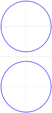
The centers of the inner housing circles are 66.5 mm apart. To determine the center positions precisely, add parallel Construction Aid endless lines 33.25 mm above and below the horizontal Construction Aid endless line. The intersections of these lines with the vertical Construction Aid endless line mark the center points of the circles. After choosing the pen "0.5 mm\Solid Line", activate "Construction Aid" snapping mode to snap to the intersections and draw two circles (Draw > Circle > Center - Point on Circle) with a diameter of 56 mm (Figure 1).
Figure 1
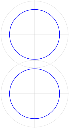
Two Construction Aid circles with a radius of 75 mm to mark the outline around the circles are now added using Construct > Construction Aid Circle > Concentric and entering the new radius using F8 (ENTER) (Figure 2).
Figure 2
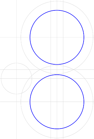
To work out the center position of the third circle which makes up part of the outline, add a parallel Construction Aid endless line 42.0 mm to the left of the existing vertical Construction Aid endless line (Construct > Construction Aid Endless Line > Parallel, numerical). A further horizontal Construction Aid endless line 42.5 mm below the horizontal Construction Aid endless line running through the center of the upper circle determines the center of the third circle part. Draw a Construction Aid circle with a radius of 16 mm from this point. In addition you can add two parallel Construction Aid endless lines 6.5 mm on either side of the vertical center Construction Aid endless line. These two lines mark the distance between the inner and outer walls (Figure 3).
Figure 3
The Construction Aid circles are joined using arcs with a radius of 6 mm. Add these arcs to the drawing using Draw > Circular Arc > Radius - Object - Object. After entering the radius identify the relevant Construction Aid circles and click on the "Forwards" key in the "Choose object" window until the arc you want to add appears on screen, and then click on OK.
Repeat the process until all the arcs have been added (Figure 4).
Figure 4
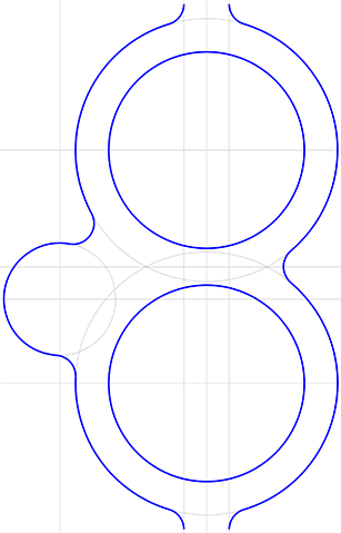
Add the missing circular arcs between the 6 mm connecting arcs using the command Draw > Circular Arc > On Circle. To do this, identify each of the relevant Construction Aid circles in turn and snap to the ends of the existing circular arcs using "Corner/ Endpoint" snapping mode (Figure 5).
Figure 5
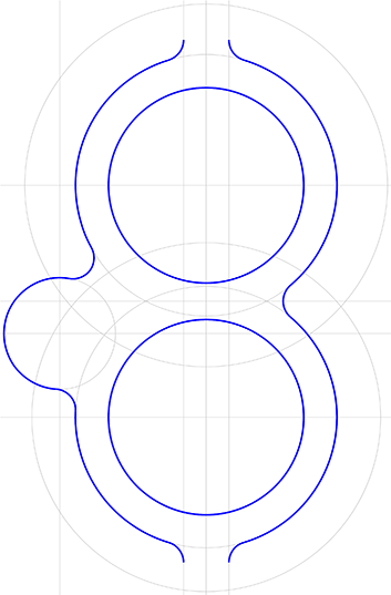
In order to be able to construct the correct transition from the inner to the outer wall, draw a Construction Aid circle concentric with the upper large Construction Aid circle with a radius of 52 mm and a Construction Aid circle concentric with the lower large Construction Aid circle with a radius of 50 mm (Construct > Construction Aid Circle > Concentric). This value is calculated from the radii of the outer wall outline (56 mm / 58 mm) minus the thickness of the wall (6 mm) (see Figure 6).
Figure 6
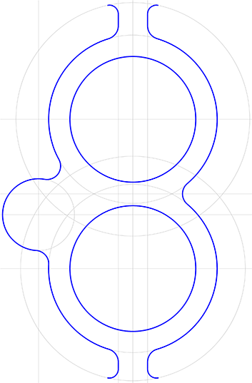
The missing circular arcs with a 4 mm radius are added next, again using Draw > Circular Arc > Radius -Object - Object. The circular arcs are tangential to the just-constructed Construction Aid circles and the vertical Construction Aid endless lines 6.5 mm from the central vertical Construction Aid endless line. Activate "Corner/ Endpoint" snapping mode and join the 4 mm arcs to the relevant 6 mm arcs using Draw > Line > Point - Point). (Figure 7).
Figure 7
This completes the inner housing wall. You can now remove all of the existing Construction Aid to make it easier to get an overview of the drawing. To do this, choose Construct > Delete Completely.
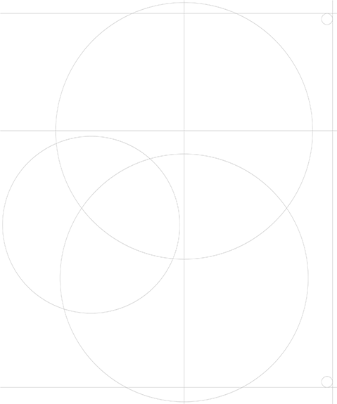
To keep a reference for the rest of the drawing, use the command Construct > Construction Aid Endless Line > Center Cross and snap circle A's center point to draw its center cross. In addition, draw Construction Aid circles with a radii of 58 mm concentric to circle A, 56 mm concentric to circle B and 40 mm concentric to circle C (see Figure 8).
Figure 8
It is not necessary to display the inner housing wall while constructing the outer outline. Choose Manage > Layers > Edit and in the dialog which appears choose the "Inner housing wall" layer. Deactivate the "Display" check box in the "Selected Layer" section. Make "Outer housing wall" the active layer and click on "Activate". The inner housing wall is now hidden from view and will not get in the way when working on the outer housing wall.
Lines must now be added to the Construction Aid. Using Construct > Construction Aid Endless Line > Parallel, numerical draw Construction Aid endless lines 67 mm to the right of the central vertical line, 53mm above and 116 mm below the central horizontal Construction Aid endless line (Figure 9).
Figure 9
To describe the outer outlines of the wall, the roundings at the top and bottom on the right edge are missing. Their radii and positions tangential to the Construction Aid endless lines are known. You can add the circle using Construct > Construction Aid Circle > Radius - Object - Object and a radius of 2.5 mm. This is shown in Figure 10.
Figure 10
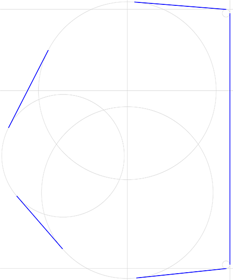
The outer outline consists of circular arcs and tangents to the arcs. Next, because the start and end points of the circular arcs are not known, draw the tangents to the Construction Aid circles which describe the outline. Choose Draw > Tangent > Object - Object and identify, one after another, both points on two circles which the line should be tangent to. You can see from Figure 11 which Construction Aid circles the lines should be tangential to.
Figure 11
It is a good idea to work with various zoom levels to place the tangent points accurately on the last drawn small circle and to view things clearly. Use Manage > Zoom > Section.
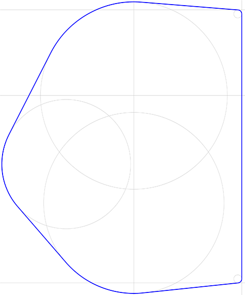
Using Draw > Circular Arc > On Circle with "Corner/ Endpoint" snapping mode active to draw the missing circular arcs and create a closed outline (Figure 12).
Figure 12
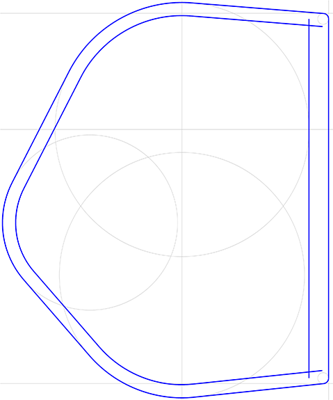
To construct a housing wall with a thickness of 6 mm, choose Draw > Line > Equidistant. Enter 6 mm in the dialog which appears. To draw an equidistant line, first of all identify the reference element and then specify which side of the reference element the equidistant line should run. Do this for all of the elements which require it. The exceptions are the two circular arcs on the right and the right-hand vertical line between them. Draw an equidistant line 9 mm to the inside of this line (Figure 13).
Figure 13
In the area where the 9 mm equidistant line and the 6 mm equidistant line intersect, both lines have to be rounded with a 4 mm radius. This is done using Trim > Round Edge, Smooth > Object - Object. Enter 4 mm into the dialog and identify both lines at the end to be rounded (Figure 14).
Figure 14
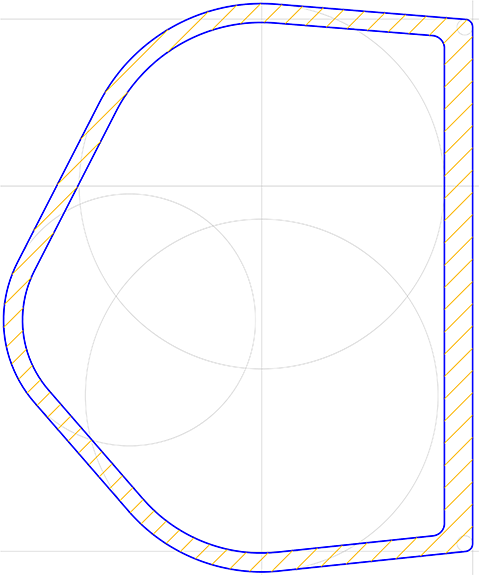
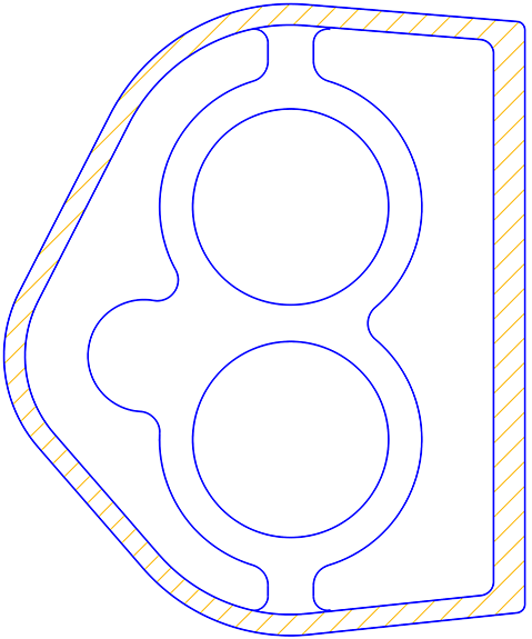
This completes drawing of the gear housing wall. In order to hatch it, choose the Draw > Hatching > Generated Surface command.
Now, identify all the visible objects. Either press F10 (SHIFT+Q) or press the SHIFT key and drag a rectangle round all the objects. For each outline to be recognized, a reference point has to be placed near to it. So place one reference point close inside the inner housing wall, and one point close outside the outer housing wall. Then terminate the point entry (click right mouse button, and if the Workflow Manager is active and appears, choose Finish Command. Alternatively, the corresponding button in the Parameter Window can be clicked). The area between the two housing walls will now be hatched (see figure 15).
Figure 15
The Construction Aid can now be turned off using the button in the Panel (Figure 16). Then, use the Manage > Layer > Edit command to display the layer "Inner housing wall" again.
Figure 16
Remember that the hatching is on a layer of its own and can be turned on and off. Layer settings for specified objects are set using Manage > Layers > Defaults.
Next, draw the circles' symmetry lines with Draw > Line > Center Cross using the pen "0.25 mm\\Dash-Dot Line Narrow". Extend the larger circle's vertical symmetry line outside the outer housing wall using Trim > Trim Object > Length / Radius to Point.
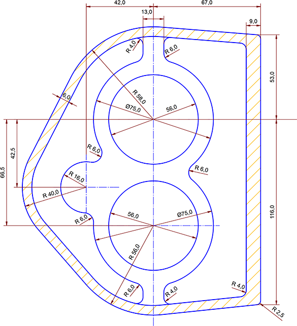
Dimension centering should be turned off for all the following dimensions by clearing the appropriate check box in the dialog. In addition, reduce the text size for all dimensions to 3.5 mm with the Annotate > Dimension Parameters command. Dimensions are applied to the radii using Annotate > Dimension > Radius, Object. The diameters can be measured by choosing Annotate > Dimension > Diameter, Objects. The distances between the walls are best measured using Annotate > Dimension > Distance, Object - Object. The remaining lengths can be measured using Annotate > Dimension > Length, Points.
Figure 17
Choose Modify > Edit > Text / Attribute to remove unwanted diameter symbols and then add a drawing frame and text fields. Finally, save the drawing with File > Save Drawing as.
|
CAD6studio Release 2026.0 - Copyright 2026 Malz++Kassner® GmbH