Parametric Compounds (Basics)
|
|
Parametric Compounds (Basics) |
www.CAD6.com |
|
Parametric Compounds are collections of standard objects with added numerical parameters ("degrees of freedom" or "freedoms") that can be changed later on. Those parameters can access global variables and attributes in blocks and groups to modify complete assemblies or drawings with a single click.
Such compound are created in multiple steps. First, all objects are combined into a compound using the Create Compound command. Once the compound has been created, it can subsequently be equipped with multiple freedoms. Each freedom modifies the location of a subset of definition points within the compound. To create complex parametric compounds, you should plan ahead and be careful which freedoms to apply in which order.
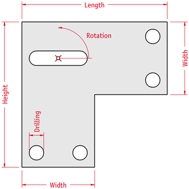
Lets's create a simple parametric compound – a bracket with several drilling holes and a long hole. The compound shall have the following parameters to be edited by the user:
Bracket with five parameters
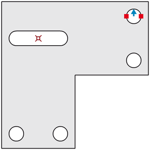
Draw the bracket with useful default sizes using the standard drawing commands of CAD6. In this case, we have a surface with several outlines and one marking at the center of the long hole (this will later be used as origin when rotating the long hole). Create a compound from these two objects using the Create Compound command. If you like, you can give it a comment such as "Bracket".
Once the compound has been created, we'll add several freedoms to it. First, let's add a freedom of type "Reference" named "Drilling" using the Add Freedom, Reference command. Choose the compound. In the appearing dialog, enter the freedom's name as "Drilling" and set both its actual and target value to the current drilling diameter ("10.0" in the sample drawing). A reference freedom is used as a local variable within a compound that can be referenced by multiple following freedoms. It does not change anything.
Any freedom can access the current target values of all preceding freedoms of that compound by using their name enclosed in the ~ character (like variables).
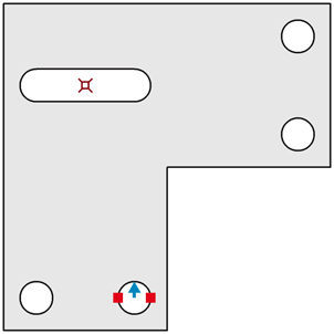
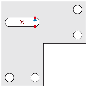
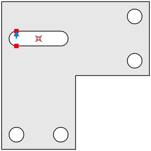
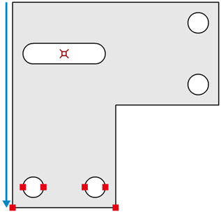
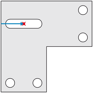
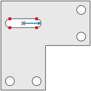
Now, let's add six freedoms of type "Radial Scaling" using the Add Freedom, Radial Scaling command, one for each of the four holes and two for the ends of the long hole. For each freedom, select the two definition points defining circular arcs (marked with a red square), then enter the center point of the hole as reference point and a point on the arc as the target point (marked with a blue arrow). This way, you will effectively define the radius of each hole. Name the freedoms "R1" through "R6" and enter "0.5 * ~Drilling~" into all of their target values:
Freedom "R1"
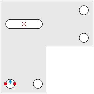
Freedom "R2"
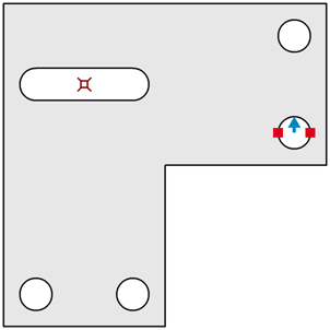
Freedom "R3"
Freedom "R4"
Freedom "R5"
Freedom "R6"
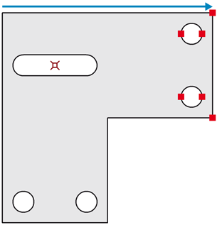
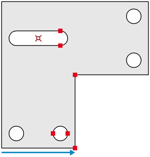
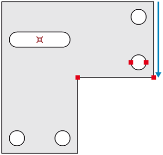
Next, add two freedoms of type "Movement" using the Add Freedom, Movement command to implement the bracket's length and height, each freedom with several points selected. Enter the start and end point of the respective edge as reference points:
Freedom "Length"
Freedom "Height"
Now, two more freedoms of type "Movement" will be added to adapt the width horizontally and vertically. The first one will be named "Width":
Freedom "Width"
The second freedom will be named "W2" and will use the first one as reference, i.e. enter "~Width~" as the target value for the second freedom:
Freedom "W2"
The next task will be to adjust the position of the long hole and its center point (the marking). This requires two more freedoms of type "Movement", named "W3" and "W4". For the vertical movement, select the long hole itself and the center point. For the horizontal movement, select the center point only. In both cases, enter "0.5 * ~Width~" as target value:
Freedom "W3"
Freedom "W4"
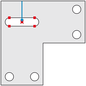
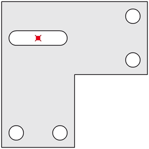
Finally, we want to be able to rotate the long hole. Add a "Rotation" freedom using the Add Freedom, Rotation command, selecting the four points defining the long hole:
Freedom "Rotation"
In order to make sure the long hole is rotated around the correct origin (which is moved by two of the freedoms defined before), we now add the marking as a dynamic origin to the "Rotation" freedom using the Set Dynamic Origin command:
Add dynamic origin to freedom "Rotation"
That's about it - the parametric compound is ready to be used. Use the standard "Edit Text" command of CAD6 to edit the freedom's values and thus change the compound's parameters.
(This compound is available as a sample drawing named Sample Compound.mkd.)
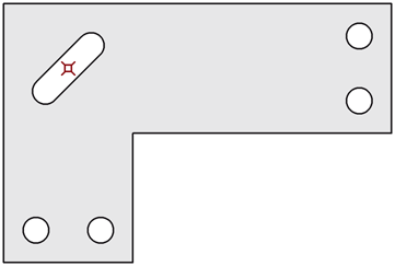
To illustrate its workings, let's change all five basic parameters to see how the compound changes:
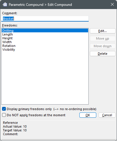
In order to make everyday working with this compound easier, you might want to differentiate between "primary" and "secondary" freedoms. Mark each freedom that you'll frequently edit (in this example: "Drilling", "Length", "Height", "Width", and "Rotation") as primary. Then, in the editing dialog for this compound, set the "Display primary freedoms only" check box to reduce the number of freedoms in the list to those you'll actually want to edit:
If the marking used as origin for the center hole disturbs you, you can easily hide it using a "Visibility" freedom using the Add Freedom, Visibility command and identifying only the marking:
Freedom "Visibility"
Name the freedom "Visibility" and enter "0.0" as target value – a target value of 0 will hide the identified points (in this case the marking). If the points are part of an outline within a curve or surface, hiding those points will hide the complete outline. If you use conditional statements in the target value (such as "{? ~Width~ < 30 {0}{1}}"), you can hide points, outlines, and objects dynamically based on numeric conditions.
If you want to access the freedom's values from the "outside", you can do so within text objects using object attributes (variables of the ~*a(UniqueID)AttributeName~ form), see Attributes.
If you have questions on how to best use Parametric Compounds, don't hesitate to contact us!
|
CAD6studio Release 2026.1 - Copyright 2026 Malz++Kassner® GmbH