Using Surfaces in Construction (Tutorial)
|
|
Using Surfaces in Construction (Tutorial) |
www.CAD6.com |
|
This chapter uses some commands that are only available in CAD6studio and/or CAD6industrie!
SettingsTutorial.mkd
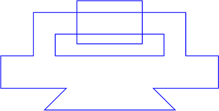
AimThis example illustrates the use of surface operations alongside the Construction Aid and trim functions when constructing a drawing. The object will be drawn solely with the addition and subtraction of surface objects and after that will have dimensions applied to it.
SurfacesChoose A4 page size with the command Manage > Pages > Edit. In order to make the example clearer, the final shape is shown as a thin dotted line in the illustrations. This is to help make it clear which part you are drawing at any time. Whenever possible, use the F8 (ENTER) key and enter dimensions directly to the dialog.
Choose the pen "0.5 mm\Solid Line Wide" and use Draw > Polygon > Rectangle) to draw a rectangle 140 mm × 70 mm (Figure 1).
Figure 1
Draw another rectangle 200 mm × 30 mm, whose bottom left corner is at the same place as the bottom left corner of the first rectangle. Use "Corner/ Endpoint" snapping mode to ensure this. To align the two rectangles, choose Modify > Align Objects > Centered, Frame Horizontal. Identify the second rectangle and, using "Corner/Endpoint" snapping mode, draw a frame exactly on top of the first rectangle. The second rectangle will automatically be aligned to this frame (Figure 2).
Figure 2
The two rectangles are now merged into one object using Trim > Trim Surface / Curve > Union (A=A+B) The two rectangles must be identified one after another. Your drawing should now look like Figure 3.
Figure 3
The next step is to add the outline of a triangle. You can see from the finished drawing that this is a right-angled triangle with a 120 mm hypotenuse (long side) (Figure 4). There are two possible ways of constructing the triangle: graphic and mathematical.
Figure 4
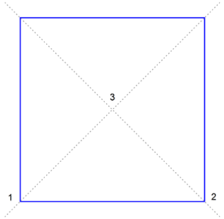
The Graphical MethodDraw a rectangle 120 mm × 120 mm anywhere on the page. Draw in the two diagonals as Construction Aid endless lines using Construct > Construction Aid Endless Line > Point - Point with "Corner/Endpoint" snapping mode active. You can determine the outline of the rectangle from this construction (Figure 5).
Figure 5
Choose Draw > Polygon > Triangle and place the corners on the two lower corners of the rectangle (1) and (2) and the intersection of the two Construction Aid endless lines (3). After you have drawn the triangle, you can delete both the square and the Construction Aid endless lines using Modify > Delete Objects.
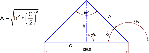
The Mathematical MethodThis method requires a little more knowledge about the mathematical construction of triangles, but is faster. Choose Draw > Polygon > Triangle. Click the mouse button to place the first point of the triangle on the page. Press the F8 key and use polar coordinates to enter the length and angle of the hypotenuse. Assuming the first point is the lower left angle, the following values have to be entered: l=120 a=0. This tells Malz++Kassner CAD6 to place a point 120 mm from the first one at a direction of 0°. Press ENTER and then F8 again to enter the position of the third point. The angle of the right side A and its length are calculated using Pythagoras" formula: The height is identical to half the hypotenuse C, as can be seen from Figure 6.
Figure 6
In the dialog, enter l=sqrt(60^2+60^2) a=135.
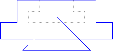
Back to the OutlineTo align the triangle correctly with the existing outline, draw a horizontal Construction Aid endless line 20 mm below the bottom line of the outline. Do this by choosing Construct > Construction Aid Endless Line > Parallel, numerical and entering 20 mm as the distance. Use Modify > Move Objects > Offset and activate "Edge" snapping mode to move the triangle onto the new line. The triangle is horizontally aligned with the outline using the Modify > Align Objects > Centered, Frame Horizontal in the same way as the two rectangles were aligned earlier.
Figure 7
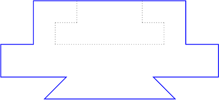
These two outlines are also merged with the command Trim > Trim Surface / Curve > Union(A=A+B).
Figure 8
Further areas have to be removed from the outline. Draw a rectangle 100 mm × 20 mm with its bottom left corner on outline corner 1 (see Figure 9).
Figure 9
This rectangle has to be aligned horizontally using Modify > Center Objects > Frame, Horizontal). Use the two symmetrical points in the outline as the corner points of the frame. Use Trim > Trim Surface / Curve > Difference (A=A-B) to unify the objects. Identify both objects one after another. A hole appears in the place of the last-drawn rectangle. This change is not visible if the larger object is filled.
You can easily check the alterations to the outline by choosing Modify > Object Properties > Edit and changing the fill mode to "both". You will see the blank space. Objects behind the outline will now be visible through the hole.
One further rectangle is to be removed. Draw a 60 mm × 40 mm rectangle and position it using Modify > Move Objects > Offset so that it covers areas approximately the same are above and below the upper part of the outline. Center the rectangle horizontally using Modify > Align Objects > Centered, Frame Horizontal).
Figure 10
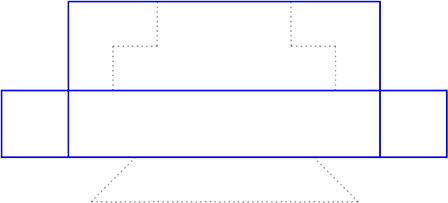
Use Trim > Trim Surface / Curve > Difference (A=A-B) to unify the objects (Figure 11).
Figure 11
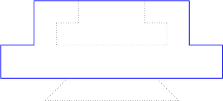
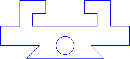
Use Draw > Circle > Center - Point on Circle to draw a circle with a radius of 14 mm and its center at outline corner point 1 (Figure 11). Center the circle horizontally using Modify > Align Objects > Centered, Frame Horizontal. This object is also cut away using the command Trim > Trim Surface / Curve > Difference (A=A-B) (Figure 12).
Figure 12
Draw a further rectangle 10 mm × 30mm and align it centrally using Modify > Align Objects > Centered, Frame Both between the points 1 and 2 (Figure 13).
Figure 13
You can now use Modify > Move Objects > Relative Values to mirror the positioned rectangle about the center. Enable the "Duplicate" check box in the dialog and enter a value for the copy position of 170 mm horizontally.
The command Modify > Mirror Objects > On Line cannot be used because an axis would have to be identified and there is no axis present.
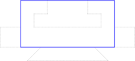
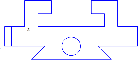
These two rectangles also have to be merged with the larger outline. However a difference does not have to be created, but they have to be combined with the large outline. This will keep the upper and lower outlines intact. Choose Trim > Trim Surface / Curve > Combine Outlines and identify all the objects to be combined. Either hold down the CTRL key and click on each object in turn or hold down the SHIFT key and drag a rectangle around all the objects. The result of this operation will not be immediately visible, however you can test it (as previously) by coloring the object using Modify > Object Properties > Edit (Figure 14).
Figure 14
Choose the pen "0.25 mm\Solid Line Narrow". Hatch the whole outline using the command Draw > Hatching > Objects (Figure 15).
Figure 15
Now the symmetry lines in the circle and the cut-throughs at left and right should be added. Click on the pen "0.25 mm\\Dash-Dot Line Narrow" and choose Draw > Line > Center Cross and then snap the circle's center point to draw a center cross which extends beyond the boundary of the circle. Use Trim > Trim Object > Length / Radius to Point to extend the vertical line upwards to roughly level with the object's upper edge.
In the cut-out on the left, turn on "Midpoint" snapping mode and use Draw > Line > Vertical to draw a vertical line. Use Trim > Trim Object > Length / Radius to Point to extend the line upwards by 5 mm. To do this, press the F8 key after identifying the line and enter 35 mm (30 mm existing line, 5 mm extension. Repeat the process with the other end, entering 40 mm (35 mm line plus 5 mm extension).
Copy this vertical line to the other cut-out by using Modify > Mirror Objects > On Line with the duplicate function (F7) turned on. Identify the line to be copied and then click on the vertical line running through the circle which is the whole outline's symmetry axis. You could also use the command Modify > Move Objects > Relative Values (Figure 16).
Figure 16
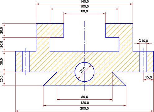
Finally add the dimensions. Apart from the circle diameter these can all be added using Dimension > Dimension > Length, Point or Dimension > Dimension > Length, Objects To be able to position the diameter dimension better, after choosing Dimension > Dimension > Diameter, Object turn off the "Close" and "Center" settings In the dimension parameters dialog (accessible by pressing SHIFT+ESC).
Place an erasing surface behind the hole's dimension and remove the diameter sign from this dimension using Modify > Edit > Text / Attribute). Your drawing should now look like Figure 17.
Figure 17
Do not forget that there can be problems using Trim > Trim Surface / Curve > Union, Trim > Trim Surface / Curve > Intersection and Trim > Trim Surface / Curve > Difference if adjacent surface edges are parallel and lie on top of each other. If possible, avoid this by making objects overlap. Further information about this can be found in the electronic reference.
|
CAD6studio Release 2026.1 - Copyright 2026 Malz++Kassner® GmbH