The Eccentric (Tutorial)
|
|
The Eccentric (Tutorial) |
www.CAD6.com |
|
This chapter uses some commands that are only available in CAD6studio and/or CAD6industrie!
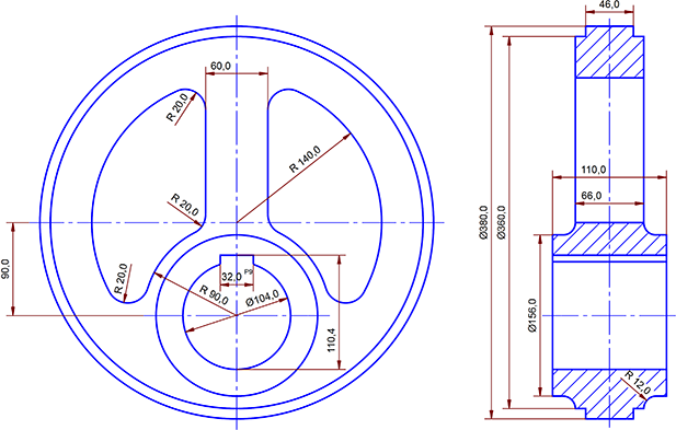
AimThis drawing of an eccentric is intended to show the use of the Construction Aid. Various construction procedures and measurements with differing parameters are used. You will learn how to generate and hatch surfaces and to merge objects from other drawings. To remove parts of the background, erasers are used as aids to drawing.
SettingsTutorial.mkd
RemarksDescriptions of choosing commands and working procedures are briefer than in the previous example. Entry of precise values is always done by pressing the F8 key or by clicking on the status window. The relevant values are entered in a standard dialog.
You should already be familiar with the snapping functions and procedures for identifying objects.
Page FormatThe eccentric is to be drawn on a landscape DIN A3 page in the scale 1:2. Choose Manage > Pages > Edit and click on the entry for "DIN A3" in the list of formats. Click on the icon for "Landscape" and then click on "OK".
Use the command Manage > Coordinate Systems > Edit. to set the scale. Click on the "View" button and then on Reduction Sales: 1:2 button. Close the dialog by clicking on "OK".
Because the drawing consists of a part with two views which use a common Construction Aid, it can make sense to insert an alignment mark before beginning drawing to make it easier to put the Construction Aid and the objects in the correct relationship. Alignment marks are used in the printing industry for example to line up printing films or plates precisely. In this example, the Construction Aid is on one film and the objects are on the other. If objects have to be moved during drawing, it is important to move the Construction Aid by the same amount. Alignment marks help you to do this. The coordinate system's origin, normally the bottom left of the sheet, is a good place for an alignment mark.
Choose Construct > Construction Aid Circle > Center - Point on Circle, press the F8 key and enter the coordinate 0 and 0 into the dialog. This places the center of the Construction Aid circle on the origin. Pressing F8 again and entering 2 in the dialog sets the Construction Aid circle's radius to 2 mm. Choose Construct > Marking > Single, press F8 again and enter 0 and 0 to place a marking at the center of the Construction Aid circle.
You can move the Construction Aid to agree with the position of the drawing by choosing Modify > Move Objects > Offset and grabbing hold of the marking with "Midpoint" snapping mode active and letting go of it on the marking with "Marking" snapping mode active.
AlignmentThe starting point of the drawing is to be the plan, the left part of the drawing. To guarantee horizontal alignment, place a horizontal Construction Aid endless line across the center of the page by choosing Construct > Construction Aid Endless Line > Horizontal, pressing F8 and entering the term (_pt+_pb)/2 into the field y. This will make the application work out the y-coordinates for horizontal Construction Aid endless lines from the coordinates of the page's upper and lower edges. If the coordinate system origin is on the page's bottom edge, the same as the default settings in mkcad6.mkd, then _pb/2 is all that has to be entered. This entry places the horizontal Construction Aid endless line half way up the page.
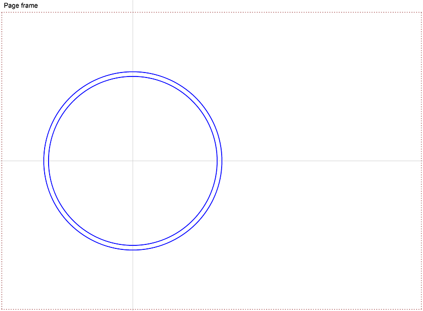
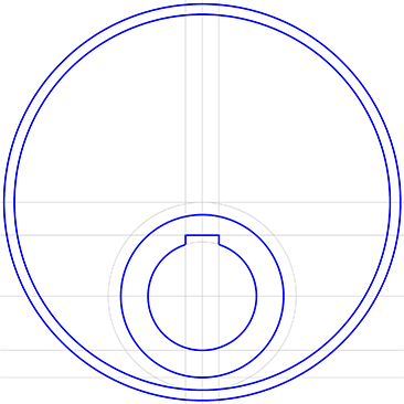
The PlanIn addition, place a vertical Construction Aid endless line approximately one third of the way across the page using Construct > Construction Aid Endless Line > Vertical The resulting intersection marks the provisional center of the plan (Figure 1). The final alignment is done at the end.
Choose the pen "0.5 mm\Solid Line Wide" and use Draw > Circle > Center - Point on Circle to draw a circle centered on the intersection of the Construction Aid endless lines. Whilst doing this, briefly activate the "Construction Aid" snapping mode using the SHIFT key. After specifying the center, press F8 and specify a radius of 190 mm.
Choose Draw > Circle > Concentric and identify the previously drawn circle. Enter a radius of 180 mm for the new circle. Your drawing should now look similar to this:
Figure 1
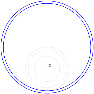
The BearingThe center of the eccentric bearing is specified next. It lies 90 mm below the intersection of the Construction Aid endless lines. Choose Construct > Construction Aid Endless Line > Parallel, numerical, enter 90 mm as the distance and identify the existing horizontal line as the reference line. Place the parallel line underneath the reference line. The Intersection of this new line and the vertical line (Point Z) is the center of the bearing. (Figure 2).
Figure 2
Using this new intersection as the center, use Construct > Construction Aid Circle > Center - Point on Circle to draw a Construction Aid circle with a radius of 52mm. Use Construct > Construction Aid Circle > Concentric to draw 2 further circles with radius of 78 mm and 90 mm (Figure 2).
The two circles can be drawn in the same command sequence. Instead of finishing the command after entering the first radius, press F8 again, enter the second radius and then finish the command (click right mouse button, and if the Workflow Manager is active and appears, choose Finish Command. Alternatively, the corresponding button in the Parameter Window can be clicked).
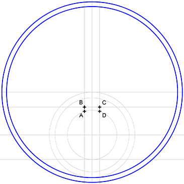
The Spring NutThese Construction Aid endless lines are used to determine the position of the spring nut. Use Construct > Construction Aid Endless Line > Parallel, numerical to draw two parallel vertical lines 16 mm on either side of the existing parallel line. This can be done in one step by first identifying the vertical line then clicking with the left mouse button to the left of the reference line and clicking with the left mouse button to the right of the reference line, then finishing the command sequence (click right mouse button, and if the Workflow Manager is active and appears, choose Finish Command. Alternatively, the corresponding button in the Parameter Window can be clicked).
To determine the depth of the nut, a horizontal Construction Aid endless line is placed through the lower quadrant of the innermost Construction Aid circle. Choose "Quadrant" snapping mode and draw a horizontal line through the lower quadrant using Construct > Construction Aid Endless Line > Horizontal with the SHIFT key held down. The spring nut is 110.4 mm from this line. Construct > Construction Aid Endless Line > Parallel, numerical is used to specify the distance exactly and draw the Construction Aid endless line.
The outline of the bearing is found from the intersections. Turn on the "Construction Aid" snapping mode and use Draw > Line > Polyline / Curve to draw the bearing's sprung nut by using the intersections (A, B, C and D in Figure 3) as the corners of the polyline. End the command sequence by clicking the right mouse button after entering the fourth corner point.
TIf you misplace one of the corner points, then you can take it back by pressing the ESC key before ending the command.
Figure 3
Complete the bearing by drawing the remaining arc using Draw > Arc > On Circle Identify the Construction Aid circle on which the arc is to be drawn and then choose as start and end points the ends of the polyline. You can have the "Corner/Endpoint", or "Construction Aid" snapping modes, or both, active.
If the arc runs in the wrong direction, you can easily change it during drawing using the relevant button from the panel. If you have finished drawing the arc in the wrong direction, change it by using the command Trim > Transform Object to > Inverted Object
Use Draw > Circle > On Circle to complete the middle concentric circle (see Figure 4).
Figure 4
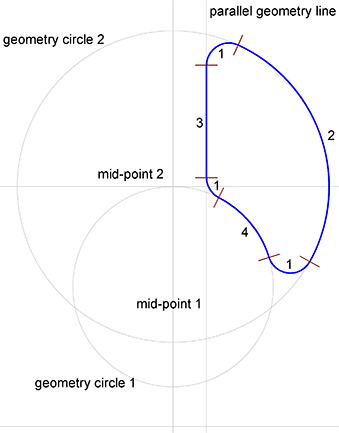
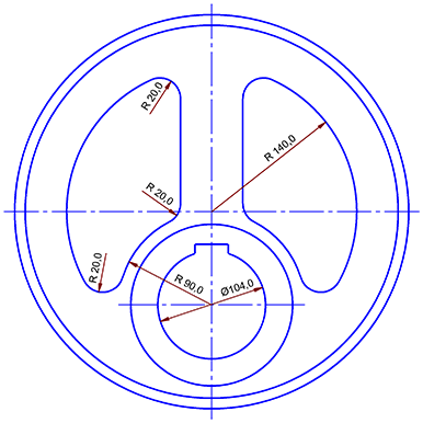
The Blank SpacesThe blank spaces in the eccentric are still missing. Only one has to be drawn: the other can be created using mirroring with the duplicate function turned on. The outline of each cut-out consists of the five circle parts (3×1, 2, and 4) as well as a line (3) (Figure 5). Of the circle parts 2 and 4 as well as the line 3, only the position of the Construction Aid on which they sit is known. The start and end points are not known.
Figure 5
The three circle parts 1 have a known radius, but their center points are not known. Their position must therefore be worked out from further information. This extra condition is that each of the three circle parts ends tangential to two further objects.
First it is necessary to draw the missing Construction Aid. Construction Aid circle 1 already exists. Use Construct > Construction Aid Circle > Concentric to draw a Construction Aid circle with a radius of 140 mm to use for circle part 2. In addition, use Construct > Construction Aid Endless Line > Parallel, numerical to draw a line 30 mm distant from the vertical Construction Aid endless line. The line (3) from the cut-out will be drawn there later.
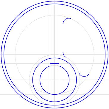
Begin to construct circle part 1 with Draw > Arc > Radius - Object - Object . Enter the radius 20 mm in the dialog field. Now identify both the Construction Aid elements to which the arc should be tangent. For the upmost arc, these are the last-drawn vertical Construction Aid endless line and Construction Aid circle two. The application will offer a choice of the arcs which it can draw. Click on the "Next" button until the variant which you want appears and then click on "OK". Repeat the process to draw the other two arcs 1 (Figure 6).
Figure 6
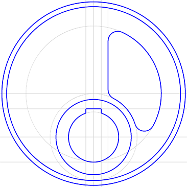
Because the tangential points are now determined, the elements two, three and four can be drawn on top of the existing Construction Aid. Choose Draw > Line > Point - Point and draw the missing straight line by clicking on the two arcs' endpoints with "Corner/ Endpoint" snapping mode active.
Choose Draw > Arc > On Circle and draw the missing arc by identifying the relevant Construction Aid element and clicking on the two arcs' endpoints with "Corner/Endpoint" snapping mode active (Figure 7).
Figure 7
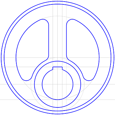
The outline for the right cut-out is now complete. Choose Modify > Mirror Objects > On Line. To be able to mirror and duplicate the cut-out in one move, press and hold down the CTRL key and identify each of the elements in the cut-out's outline. Holding down the CTRL key makes it possible to identify more than one object for manipulation at the same time. Release the CTRL key after identifying all the elements in the outline. Next, it is necessary to identify the axis of mirroring. Press the CTRL key again to activate the duplicate function. You will know that it is active because a "+" appears on the crosshair. Identify the vertical Construction Aid endless line running through the center of the circle as the rotation axis by clicking on it. The mirroring should now appear symmetric to the original (Figure 8).
Figure 8
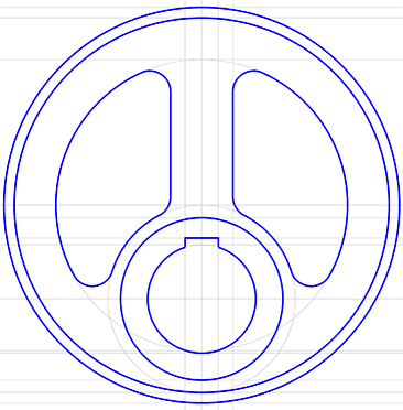
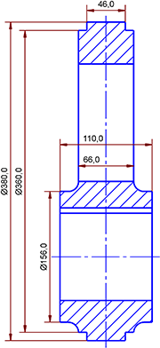
Apart from the mid lines, the section indicator and the dimensions, the plan is now complete. Before they are added to the drawing, the section drawing should be drawn.
The Section ViewTo make drawing the section as easy as possible, the most important points from the eccentric are to the side view with the help of the Construction Aid. With the "Quadrant" snapping mode active, use Construct > Construction Aid Endless Line > Horizontal to insert horizontal Construction Aid endless lines at the upper and lower quadrants of the three outermost concentric circles and the two inner bearing circles. This produces a total of nine new horizontal Construction Aid endless lines. The innermost bearing circle already has a Construction Aid endless line in its lower quadrant which does not have to be drawn again (Figure 9).
Figure 9
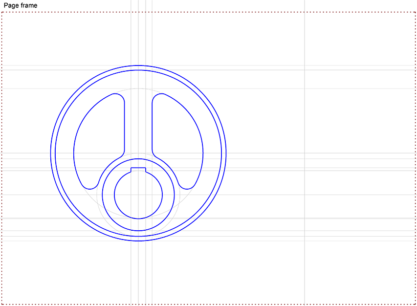
Use Construct > Construction Aid Endless Line > Parallel, numerical to place a vertical Construction Aid endless line 360 mm to the right of the eccentric's central vertical Construction Aid endless line. This line is the central vertical of the sectional drawing. If it proves necessary to move the view to get space, we remind you of the tip concerning moving the Construction Aid at the start of this chapter.
The page should now look like this:
Figure 10
Because the sectional view is completely symmetrical, it is enough to draw half of it and then mirror all the objects about the center line with the duplicate function turned on. You have already used this function whilst drawing the cut-outs in the plan view.
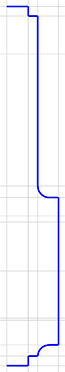
Choose Construct > Construction Aid Endless Line > Parallel, numerical and place three vertical lines 23 mm, 33 mm and 55 mm to the right of the axis of rotation. The easiest way of doing this is to press SHIFT+ESC (N) to restart the command and enter a new value.
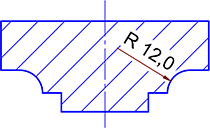
All the intersections needed to draw the sectional view are now in place. Nest, the rounded shapes for the bearing are drawn. They both have a radius of 12 mm and are tangent to two Construction Aid endless lines. Choose Draw > Arc > Radius - Object - Object, enter the radius 12 mm and identify the tangential Construction Aid endless lines. Choose the desired variant.
Figure 11
Now the remaining intersections are joined using a polyline drawn using Draw > Line > Polyline / Curve and the "Construction Aid" snapping mode turned on (Figure 12).
Figure 12
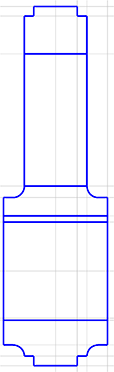
Choose Modify > Mirror Objects > On Line and, holding down the SHIFT key, drag out a rectangle around all parts of the sectional drawing. Release the key. This has identified the objects for the following operation. Press and hold down the CTRL key to activate the duplicate function and identify the left of the four vertical Construction Aid endless lines as the reference line (axis of rotation).
To complete the outline, draw the five horizontal lines using Draw > Line > Point - Point with both "Intersection" and "Construction Aid" snapping modes active. This is needed to ensure that the lines snap correctly to the intersection points on the mirrored side of the drawing as the objects intersect with both horizontal and vertical Construction Aid endless lines (Figure 13).
Figure 13
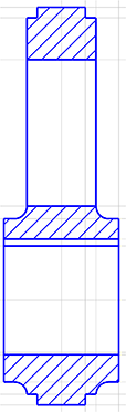
Surfaces and HatchingsThe Construction Aid is not needed during the next step. It is best if you turn it off with the button in the panel or with Construct > Display Construction Aid.
Three areas in the sectional view need to be hatched. It is necessary to temporarily generate a surface from the objects surrounding the areas to be hatched. To generate a surface, all the objects surrounding the surface have to be identified. Make sure that the button for "Inside" area mode is pushed in. Change to the pen "0.25 mm\Solid Line Narrow" and choose Draw > Hatching > Generated Surface and, holding down the SHIFT key, drag a box around the surface which is to be generated. The future surface must lie completely within the box, or all the line parts may not be identified. Specify a reference point inside the area of the new surface.
Carry out a similar procedure for the other two surfaces (Figure 14).
Figure 14
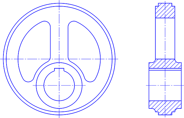
AdditionsNow, the symmetry lines are added. Turn the Construction Aid on, choose the pen "0.25 mm\\Dash-Dot Line Narrow" and draw the symmetry lines on the Construction Aid endless lines in the sectional view using Draw > Line > On Line. The lines should extend a little way beyond the eccentric's edge.
The center lines on the plan view are drawn simply by choosing Draw > Line > Center Cross and snapping the outermost circle's center point. The horizontal center line of the bearing is also drawn using Draw > Line > On Line. The Construction Aid can now be finally turned off (Figure 15).
Figure 15
Adding Dimensions to the Sectional ViewChoose the pen "0.25 mm\Solid Line Narrow". With the exception of the radius, all the dimensions are applied to the sectional view using Annotate > Dimension > Length, Point The preset parameters can be used for the dimensions outside the objects. To work out the start and end points of the lengths, activate the "Corner/ Endpoint" snapping mode. For the dimensions inside the body, restart the command using SHIFT+ESC and clear the "Center Dimension" check box. This makes it possible to position the dimension to the left of the central vertical line. For the 66 mm width dimension turn off the check box for extension lines as well and snap to the lower corners of the topmost surface. Because there are no extension lines, the dimension can be moved downwards as far as wished.
Next, choose Annotate > Dimension > Radius Object, identify the radius and place the dimension in the hatching.
Figure 16
The EraserTo clear an area for the radius' dimension in the hatching, use the eraser. Every object which is drawn has a position relative to the objects drawn before and after it. You can think of the objects as playing cards, which, when placed on the pack, partly or completely cover the underlying cards.
Use the command Draw > Polygon > Freeform / Surface to place a surface over the dimension which will "rub out" the background and only allow those objects to appear which are "above" that surface (i.e. drawn later). Then, choose the command Modify > Object Properties > Edit, identify the previously drawn surface and set its filling mode to "Eraser" (the fourth of the five available filling modes).
Objects can be brought to the front or sent to the back. This is necessary in this case because the eraser - to allow calculation of the dimension - was the last-drawn object. Choose Modify > Change Order > To Front and click in the center of the erasing surface, under which the dimension lies. (It is also possible to use Modify > Change Order > To Back and move first of all the erasing surface and then the hatching to the back.) Bear in mind that the erasing surface must be identified at its edge. The erasing surface should now block out part of the hatching and the dimension should be clearly visible (Figure 17).
Figure 17
Add the 'Ø' symbol to the vertical dimensions by choosing Modify > Edit > Text / Attribute identifying each dimension in turn and entering the 'Ø' symbol in the Pre-Text field (do this by clicking on the relevant button) and clicking on "OK".
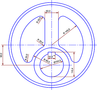
Adding Measurements to the Plan ViewNow, measurements are added to the plan view. Firstly, apply measurements to the 20 mm radii in the left-hand cut-out. Choose Annotate > Dimension > Radius, Object and deactivate the "Center Dimension" check box in the parameter dialog (accessible by pressing SHIFT+ESC). This makes it possible to place the dimension at a suitable point on the dimension line. Identify a radius, choose the dimension line direction between the center point and the radius and place the end of the line at the center by clicking on the circle's edge with "Midpoint" snapping mode turned on. Pull the dimension to the correct position.
Proceed in the same way with the cut-out's 90 mm and 140 mm radii. The "Center Dimension" check box should also be turned off when applying dimensions to the inside diameter of the bearing. This is necessary because a separate set of parameters is stored for each dimension variant. For the inner radius choose Annotate > Dimension > Diameter, Object, to put the 'Ø' character in the Pre-Text automatically (Figure 18).
Figure 18
Next, the length measurements are applied. Because none of the measurements is concerned with a single object, the command Annotate > Dimension > Length, Point must be used. The corners at which the 32 mm and 60 mm extension lines begin are used as snapping points. The dimension also has to be positioned by hand in this case. Do not forget to turn the extension lines on again. To measure the 32 mm distance, activate the Tolerances check box in the dimension parameters dialog so that you can enter P9 as the upper tolerance in the Tolerance dialog which appears later.
To apply a dimension of 110.4 mm to the sprung nut in the drawing, use the top intersection of the nut with the central vertical line and the and the quadrant point of the circle (or the intersection of the circle and the central vertical line) as snapping points.
Finally, the distance from the midpoint to the center of the eccentric (90 mm) is added. So as not to cover the dash-dot symmetry line, the extension lines can only start at the ends of the two dash-dot lines. It is necessary to keep the dimension lines vertical. Do this by activating the "Center Dimension text" and "Adapt Dimension text" check boxes in the Dimension dialog, activate "Corner/Endpoint" snapping mode and click on both ends of the dash-dot line. You can now set the dimension line's orientation. Press the F8 key and enter 90°. Now you have only to position the dimension line in the usual manner (Figure 19).
Figure 19
Drawing Frame and Text BoxNow a standard template is to be added. Select all the objects in the drawing with Extra > Permanent Selection > Set and pressing F10. This makes it possible, after inserting the template, to move the selected objects but not the newly added ones.
Now open the library containing those templates (001_Title_Blocks_DIN_6771.mkl) using the Library > Manage Libraries command. Then use the Library > Block > Insert command to choose the DIN A3 Landscape block in the Frames folder and place it in the drawing. Once finished, select the Type 4 block from the Title Blocks folder and place it in the lower right corner of the frame.
Before the next step, you should make sure that you placed one of the pass marks referred to earlier otherwise it will be much harder to align the Construction Aid after the centering. Center all the selected objects in the free drawing area using Modify > Align Objects > Center, Frame Both. To identify all the selected objects (but not the merged objects) press the F12 key and choose as the area in which everything should be centered the inner upper left corner of the drawing frame and the upper right corner of the text box. All the selected objects can now be deselected by choosing Extra > Permanent Selection > Clear and pressing F10.
Finally you can use the command Annotate > Text > Standard to generate the necessary text to go in the text box. Save the drawing using File > Save Drawing as.
Alternative Construction MethodsThe sprung nut and the cut-outs can also be constructed by using standard objects and trimming them. Try to draw the eccentric without referring to the tutorial. Use your own ideas and in case of difficulty, refer to the electronic reference.
|
CAD6studio Release 2026.0 - Copyright 2026 Malz++Kassner® GmbH