The Ballhead (Tutorial)
|
|
The Ballhead (Tutorial) |
www.CAD6.com |
|
This chapter uses some commands that are only available in CAD6studio and/or CAD6industrie!
AimThis example should make both principle methods of drawing using the Construction Aid and trimming functions. Note that in practice using just one method of construction is very rare.
SettingsTutorial.mkd
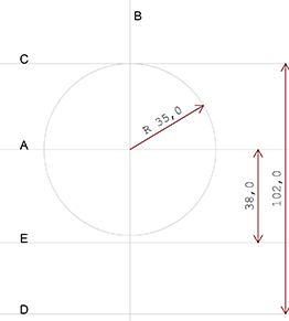
The Ballhead (Construction Aid)Use Construct > Construction Aid Endless Line > Horizontal and Construct > Construction Aid Endless Line > Vertical to draw to lines (A and B) whose intersection places the center of the ball head as close as possible to the center of the page.
Next, draw a Construction Aid circle with a radius of 35 mm using the intersection as the center (Construct > Construction Aid Circle > Center - Point on Circle). Use Construct > Construction Aid Endless Line > Horizontal) to draw a horizontal Construction Aid endless line through the upper quadrant point of the Construction Aid circle.
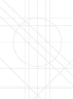
Use Construct > Construction Aid Endless Line > Parallel, numerical) to draw horizontal Construction Aid endless lines 102 mm below the Construction Aid endless line through the upper quadrant point and 38 mm below the horizontal center Construction Aid endless line. The Construction Aid should now look like Figure 1.
Figure 1
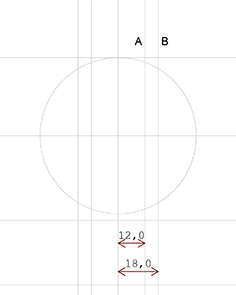
Next, construct parallels 12mm and 18 mm to the right and left of the central vertical Construction Aid endless line using Construct > Construction Aid Endless Line > Parallel, numerical (Figure 2).
Figure 2
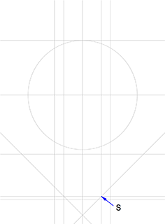
Draw a parallel Construction Aid endless line 2mm above the bottom horizontal Construction Aid endless line. Use the key combination SHIFT+ESC to restart the command. This new Construction Aid endless line will be used later when drawing the chamfered section.
Use Construct > Construction Aid Endless Line > Angle to Line to draw a line at 45° on the right side and -45° on the left side to indicate the position of the chamfer. Use the intersection of the 12 mm vertical Construction Aid endless line with the new horizontal Construction Aid endless line (S) as the snapping point. Repeat the process with the angle of 45° on the opposite side (Figure 3).
Figure 3
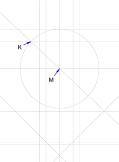
Draw a horizontal Construction Aid endless line 24 mm above the horizontal symmetry line using Construct > Construction Aid Endless Line > Parallel, numerical.
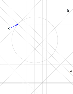
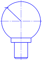
The left hand intersection of this new Construction Aid endless line with the Construction Aid circle is one end of the center line of the ball head's blank space (Figure 4, K). The other end of this center line lies at the center of the circle (M). Use Construct > Construction Aid Endless Line > Point - Point.
Figure 4
Use Construct > Construction Aid Endless Line > Parallel, numerical to draw lines 10 mm above and below this line (Figure 5).
Figure 5
To determine the depth of the blank space, use Construct > Construction Aid Endless Line > Angle to line to draw a line at 90° to the center line M which passes through the intersection of the center line M with the Construction Aid circle. Use Construct > Construction Aid Endless Line > Parallel, numerical) to draw parallel B 45 mm from the new Construction Aid endless line (Figure 6).
Figure 6
From the Construction Aid to the ObjectsSo far, you have drawn a rather complex Construction Aid. It contains all the intersections and elements needed to draw the objects. Now you can begin to draw the objects themselves. Make use not only of the "Construction Aid" snapping mode, but also of the zoom functions, as some of the intersections are close together.
Choose the pen "0.5 mm\Solid Line Wide" and begin to draw the two circle parts using the command Draw > Arc > On Circle (Figure 7).
Figure 7
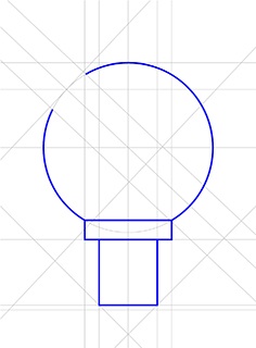
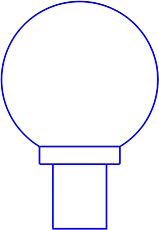
The next step is to draw the two rectangles underneath the ball head using the command Draw > Polygon > Rectangle Check the position of the rectangles against the original drawing (Figure 8).
Figure 8
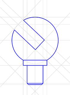
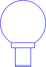
Complete the object by drawing the missing line sections (the blank space and the chamfered section) using Draw > Line > Polyline / Curve. Note that the bottom corner point of the blank space does not lie on the central vertical Construction Aid endless line but is a product of the two diagonal Construction Aid endless lines. (Zoom in on this area before locating the intersection). See Figure 9.
Figure 9
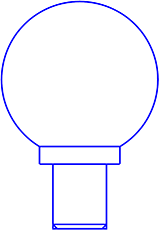
Next, the central lines are drawn. Select the pen "0.25 mm\\Dash-Dot Line Narrow" and draw the missing circle part (in the blank space) using Draw > Arc > On Circle .
Use Draw > Line > Center Cross to add the ball head's horizontal and vertical center lines at the same time. To extend the vertical line below the bottom of the object, choose Trim > Trim Object > Length / Radius to Point, identify the lower part of the line and click on the point to which the line is to be extended. Use Draw > Line > On Straight Line to draw the blank space's center line.
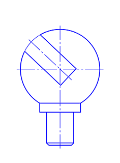
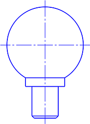
The Construction Aid can now be turned off using the button in the panel or by pressing F9 (Figure 10).
Figure 10
The 24 mm and 36 mm dimensions can be added using Dimension > Dimension > Length, Object and simple identification. Choose whatever distance you wish from the object in the parameters dialog (accessible by pressing SHIFT+ESC). To place the 36 mm dimension turn the "center dimension" check box off.
The 20 mm width of the blank space is measured using the command Dimension > Dimension > Distance, Object·Object. To make the dimension arrows point inwards choose the Orientation: Rotated setting in the parameters dialog.
All of the other dimensions are added using Dimension > Dimension > Distance, Object·Point. Choose the dimension line's orientation from the icons in the dialog box.
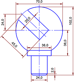
Your drawing should now look like figure 11.
Figure 11
Finally, add the missing text and symbols using Modify > Edit > Text / Attribute. If the chamfer dimension text (2.0×45º) lies within the dimension lines, you can correct this using the command Dimension > Edit Dimension > Position by clicking first on the dimension text and then on its new position (Figure 12).
Figure 12
In conclusion, as in the previous example of the eccentric cam a frame can be placed around the drawing, a text box added and the ballhead centered in the frame.
The Ballhead (Trimming)When working with trimming functions, in general complete objects are drawn and then cut to size using the trimming functions. Even if you prefer to work using Construction Aid functions, it is a good idea to work through the following example as it explains several important principles for working with trimming functions.
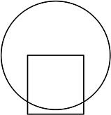
Choose the pen "0.5 mm\Solid Line Wide" and draw a rectangle 38 mm high and 36 mm wide approximately in the center of the page using the command Draw > Polygon > Rectangle. Now construct a circle centered on the midpoint of the top side of the rectangle with a radius of 35 mm using the command Draw > Circle > Center - Point on Circle and with "Midpoint" snapping mode active (Figure 13).
Figure 13
After choosing Trim > Trim Object > Cut Out click inside the part of the circle which overlaps the rectangle and then, with "Intersection" snapping mode on, click on the two points where the circle and rectangle intersect. Your drawing should now look like this:
Figure 14
Now use Trim > Trim Object > Resolve Completely to split the rectangle into individual lines. Press the DEL key (this activates the Modify > Delete Objects command) and click on the top edge of the rectangle. If the complete rectangle disappears, then the rectangle was not split up properly; use the UNDO command (Edit > Undo) to restore the rectangle (Figure 15).
Figure 15
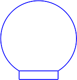
Join the ends of the arc by using Draw > Line > Point - Point with "Corner/Endpoint" snapping mode active. Trim the vertical lines to the new horizontal line using the command Trim > Trim object > Length / Radius to Object. To do this, click first on the upper part of the line to be trimmed and then on the object, until the line is the correct length.
Figure 16
For the lower part of the ball head, draw a rectangle 24 mm wide and 102 mm minus 35 mm minus 38 mm (29 mm) high somewhere on the page. This is the height of the ballhead minus the height of the parts already drawn. This sum can be entered directly as simple mathematical operations are allowed here. Choose "Midpoint" snapping mode and the Modify > Move Objects > Offset command. Place the reference point on the middle of the rectangle's top edge and move it to the middle of the previously drawn object's bottom edge (Figure 17).
Figure 17
Use Draw > Line > Parallel, numerical to draw a line 2mm below the last drawn rectangle using "Edge" snapping mode to get the ends of the line in the right place (Figure 18).
Figure 18
The next step is to create the chamfer at the bottom of the ballhead. Using Draw > Line > Angle to Line draw a 45° line in the corner. Turn on "Corner/ Endpoint" snapping mode when specifying the start point. When the start point has been chosen, the application will show a dialog allowing you to choose a reference line, shown during the process. This Construction Aid endless line lies on the previously specified line whose endpoint still has to be specified. All the intersections of this reference line can be snapped to using a combination of "Intersection" and "Construction Aid" snapping modes. Use the intersection of the reference line with the lower edge of the ballhead as the snapping point. The reference line is automatically turned off when the command has been carried out.
Carry out the same procedure for the second chamfer, but using an angle of -45° (Figure 19).
Figure 19
Now it is necessary to remove the corners next to the chamfers. Remember that these corners are actually part of the surrounding rectangle. To trim them, the rectangle must first of all be split into individual lines. Choose Trim > Trim Object > Resolve Completely and click on the rectangle. Before proceeding further, it is a good idea to zoom in on the area using Manage > Zoom > Section.
After choosing Trim > Trim object > Length / Radius to Object click first on the end of the line to be shortened and then on the object to which it is to be shortened (Figure 20).
Figure 20
The construction of the blank area is more complex. In order to get some necessary intersections, the symmetry lines are drawn in at this stage. Change to the pen "0.25 mm\Dash-Dot Line Narrow" and use Draw > Line > Center Cross to draw the arc's center cross. Make the vertical line longer using Trim > Trim Object > Length / Radius to Point (Figure 21).
Figure 21
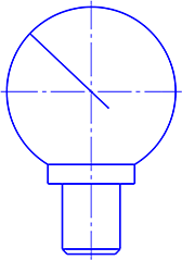
Change back to the pen "0.5 mm\Solid Line Wide" for the remaining steps. Using Draw > Line > Parallel, numerical draw a short line 24 mm above the horizontal line so as to create an intersection with the arc's left side. Join this intersection to the center using the command Draw > Line > Point - Point). See Figure 22.
Figure 22
Remove the short horizontal line using Modify > Delete Objects (or by using the DEL key) and make the diagonal line longer by choosing Trim > Trim Object > Length/Radius to Point. Identify the lower part of the line, press F8 and enter 45 mm as the length (Figure 23).
Figure 23
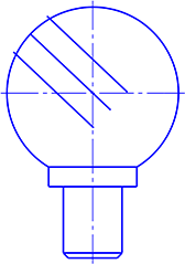
The edges of the blank area are generated next using the symmetry axis just drawn as a model. Choose Modify > Move > Perpendicular and activate the duplicate function by pressing F7 or clicking on the button in the panel. Identify the diagonal as the object to be moved and as the reference object. The reference point can be placed as desired. Press F8 and enter 10mm as the distance. (Note the direction of the arrow in the dialog. It shows the direction of movement.) Repeat the process using a distance of -10 mm (Figure 24).
Figure 24
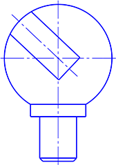
Use the command Draw > Line > Point - Point with the "Corner/Endpoint" snapping mode turned on, to draw a line joining the ends of the new lines. Trim the upper ends of the lines to the arc radius using Trim > Trim Object > Length / Radius to Object). See Figure 25.
Figure 25
Now, change the pen properties of the middle diagonal line from pen "0.5 mm\Solid Line Wide" to pen "0.25 mm\\Dash-Dot Line Narrow" with Modify > Object Properties > Edit. The "Fixed" check box is enabled automatically after choosing this command. Extend the blank space's symmetry line outside the edges of the blank area using Trim > Trim Object > Length / Radius to point (Figure 26).
Figure 26
The rest of the procedure, such as adding dimensions and text and centering the drawing, follows the same methods as when the Construction Aid is used. Finally, save the drawing with File > Save Drawing as.
|
CAD6studio Release 2026.1 - Copyright 2026 Malz++Kassner® GmbH