Creating a 3D Part (3D Introduction)
|
|
Creating a 3D Part (3D Introduction) |
www.CAD6.com |
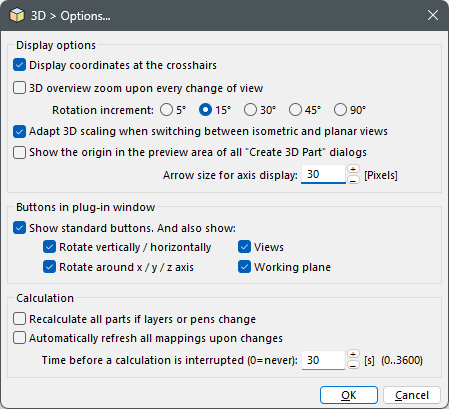
SettingsBefore starting the creation of the first part, you should take some time to familiarize yourself with some settings. Choose the 3D > Options command.
Options
First of all, we recommend that you activate the "Show space axes" option. By default, it is deactivated in order not to disturb the work in 2D. But when working in 3D, it is very helpful to grasp the current orientation of the space.
Furthermore, you should adapt the default properties for "3D Construction" and "3D Parts" to your standard template, especially concerning layers. If you using the current standard template, you can use the layers "3D Construction" and "3D Parts" intended for that purpose. A consequent use of these layers will allow you to show and hide the complete 3D parts subsequently.
Finally, you should decide if you want to have virtual points, axes, edges, corners and end points highlighted. This can help when trying to identify them, but will lead to some confusion in complex constructions due to the high number.
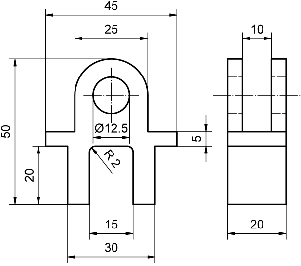
Creating the 2D DrawingThe following figure shows the part that we want to create in a 2D drawing with complete dimensions.
2D views of the 3D part to be created
To create this part, we will need two parts: First a 20 mm thick extrusion of the complete outline of the front view, and second a 10 mm thick extrusion of an auxiliary outline (drawn with a dotted line in the figure below) that will be used to create the "slit".
Both outlines should be drawn intersecting each other to have them already aligned correctly:
Outlines for the 3D elements creation
We recommend using the (2D) construction aid to easily create the required outlines: First, create all vertical and horizontal lines with numerically entered distances, then create the two circles. Finally, create the outer outline using the Draw > Polygon > Contour Tracking Surface command and combine it with the inner circle (representing the drill hole) using the Trim > Surface / Curve > Combine Outlines command.
The auxiliary outline can be created as an arbitrary polygon (or a quadrangle) by clicking the two corner points of the outer outline and entering two additional, arbitrary points outside the outer outline.
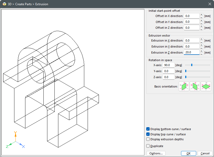
Creating the Single ElementsOnce the outlines have been created in 2D, we will now create the single elements in 3D. In our example, this is done twice using an extrusion. Select the 3D > Create 3D Parts > Extrusion command and identify the outer outline. As for the reference point, it would be best to snap one of the two common points of the two outlines to have them aligned correctly. A dialog will appear in which you can enter the extrusion parameters. First, choose the desired basic orientation by means of the preview (in our example, we chose the second button), then enter the required extrusion depth (20.0 mm in Z direction).
Extrusion parameters for the outer outline
The second element based on the auxiliary outline is created the same way, but this time with an extrusion depth of 10.0 mm in Z direction. As a result, you should now have two 3D parts that are correctly aligned towards each other in 3D space although their display seems confusing at first since the two parts are still independent and thus the display surface sorting is not yet correct (the extrusion of the outer outline has been dyed in blue):
Created 3D parts
Now, the second extrusion must the moved by 5 mm to be at the correct placement relative to the first extrusion. You can use either 3D > Move / Copy 3D Parts > Along Edge or 3D > Move / Copy 3D Parts > In Y Direction to do so. After choosing the part (and identifying the edge, if necessary) press the F8 key to initialize a numeric coordinate entry. An arrow in a small field in the dialog will show you which movement direction is positive so that you can decide whether you have to enter "5" or "-5" as offset. The result should look as follows:
3D parts, correctly aligned
Combining the Single ElementsNow we can combine the two single elements into one final part. Select the 3D > Edit 3D Parts > Difference (A=A-B) command, choose the element created from the outer outline as part A and then the part created from the auxiliary outline as part B. The result should now look as follows:
Finished 3D part
This is our final 3D part.
Subsequent Modification of the 3D PartThe part created this way remains editable for the most part. Using 3D > Edit Parts Tree, you can e.g. change the extrusion depths of the two elements to 40.0 mm and 30.0 mm to get a "wider" part:
Modified 3D part
Furthermore, you can use the 3D > Edit 3D Parts > Split into Separate Parts command to resolve the part back into its single elements (i.e. the two extrusions). If you want to modify the outline of one of the extrusions, you can use 3D > Edit 3D Parts > Extract Basic 2D Objects to make the outline available for editing again.
Had the drill hole not been created as an integrate part of the outer outline, but instead been added to the part as a difference with a cylinder, it would also be possible to subsequently change the drill hole’s diameter or to shorten the cylinder in order to limit the drill hole to one of the two sides. As you can see, it can be worthwhile to spend more time in constructing a part in the beginning to increase the number of subsequent modification possibilities!
|
CAD6studio Release 2026.1 - Copyright 2026 Malz++Kassner® GmbH