Trouser Leg (Tutorial)
|
|
Trouser Leg (Tutorial) |
www.CAD6.com |
|
This chapter uses some commands that are only available in CAD6studio and/or CAD6industrie!
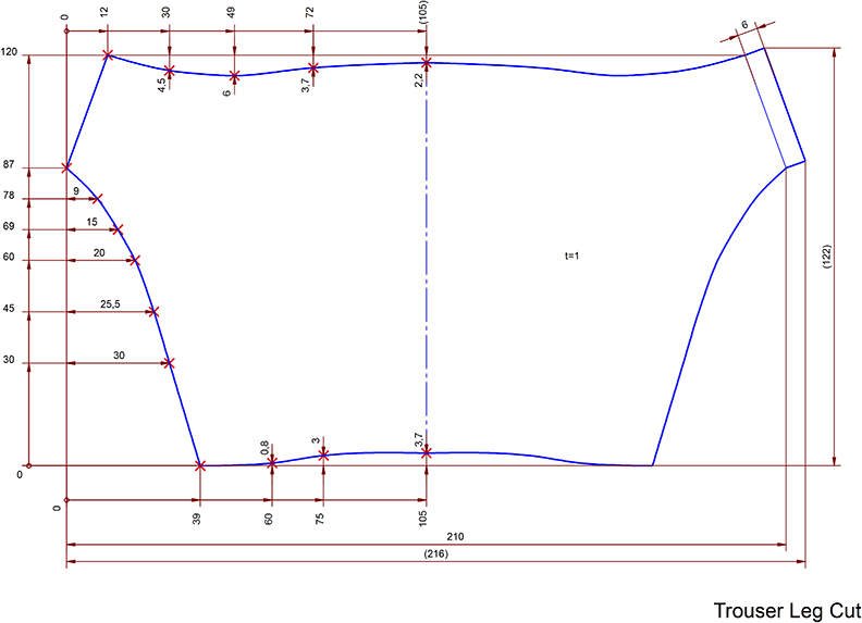
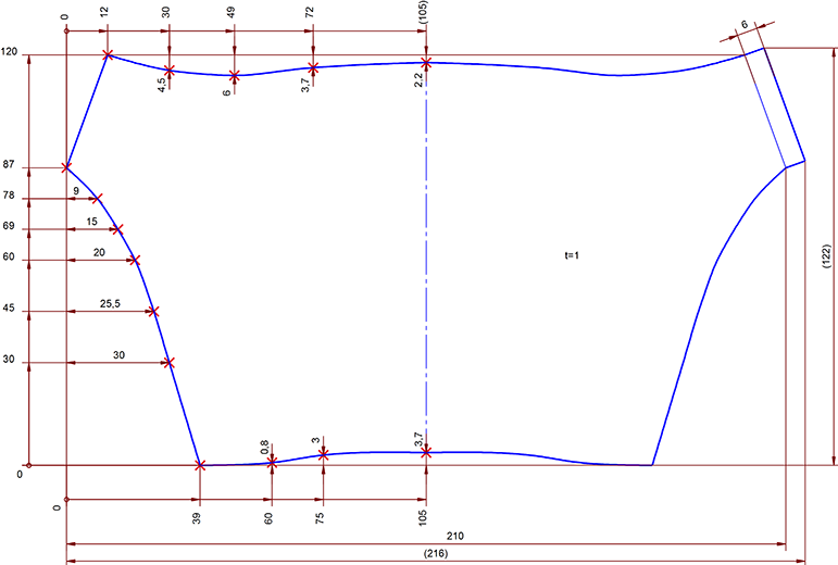
AimThis example demonstrates the use of Spline curves in technical drawing and further dimension measurement techniques.
SettingsTutorial.mkd, with the page set to landscape orientation.
BasicsThe most important parts of the design are three curves which determine the outline. The curves have defined fixed points and during drawing a Spline curve is passed through those points. As the drawing is virtually symmetrical, it is only necessary at this time to draw the left hand side, which can then be mirrored with the duplicate function active.
Begin the drawing by using Manage > Coordinate System > Set Origin to place the drawing origin in the page's bottom left corner. This is not absolutely necessary but it makes the representation easier, as some of the points would either lie on the edge of the page or would have to have an offset value added to their coordinates.
The points are set using markings, choose Construct > Marking > Single, press F8 and enter the first point's coordinates. Use the values from the drawing at the beginning of this chapter. A reference point measurement is chosen, and the values are relative to the origin. For your convenience, so-called redundant measurements, calculated from existing measurements, are given in brackets. If possible, the use of these measurements in drawings should be avoided.
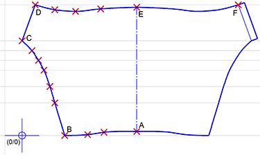
For the lower curve, the following points have to be entered using markings: (39; 0) (60; 0.8) (75; 3.0) (105;3.7). See Figure 1.
Figure 1
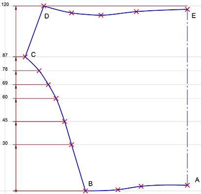
Proceed in the same way for all the points in the left half. To specify the position of the upper curve, use the formula y=120-a where a is the distance to the highest point of the curve (Figure 2).
Figure 2
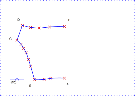
The outline of the left side of the trouser leg consists of three curves: AB, BC, DE and a line CD. Note that the curves AB and BC are two separate objects. They must not be drawn as a single object as they form a corner at point B. Corners cannot be defined within a Spline curve. The command must be ended at point B and then restarted at the same point.
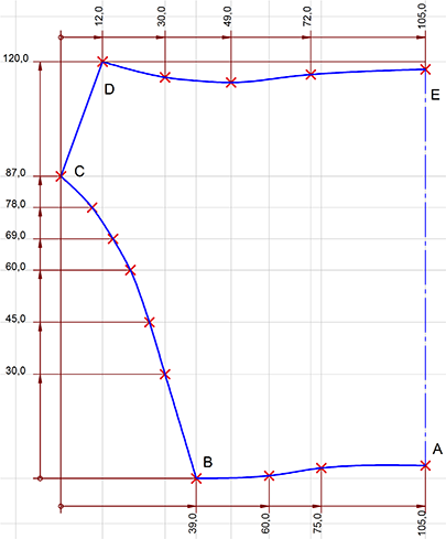
Choose the pen "0.5 mm\Solid Line Wide" to draw the rest of the objects. Activate "Markings" snapping mode and join the points with a Spline curve (Draw > Spline). To finish drawing a Spline, click the right mouse button, and if the Workflow Manager is active and appears, choose Finish Command. Alternatively, the corresponding button in the Parameter Window can be clicked. Join points C and D using Draw > Line > Point - Point with "Markings" snapping mode active (Figure 3).
Figure 3
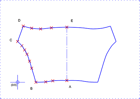
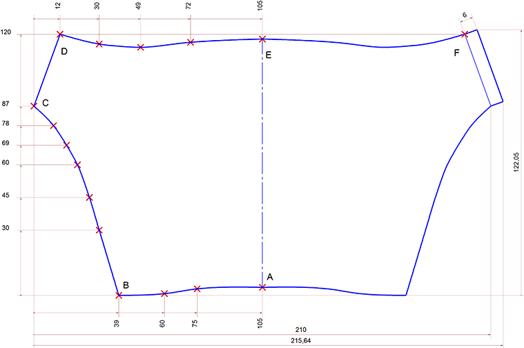
Next, the symmetry axis is drawn between points A and E. You can now mirror and duplicate the outline using Modify > Mirror Objects > On Line. Hold the CTRL key down whilst identifying the four objects. Release it and then press it again. This activates the duplicate function. Now identify the symmetry axis to mirror and duplicate all the selected objects (Figure 4).
Figure 4
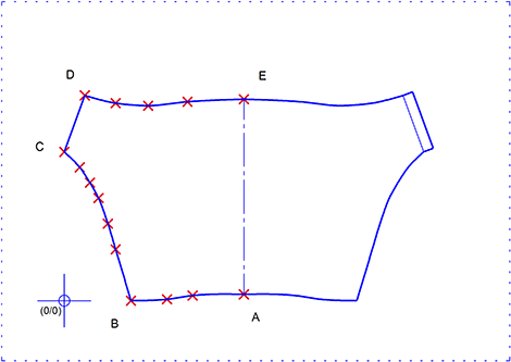
To draw the tongue on the right hand side, move the existing line by 6 mm parallel to itself with the duplicate function active. Choose Modify > Move Objects > Perpendicular and identify the line on the right. Choose the line itself as the reference line. Press F7 to turn on the duplicate function and then press F8 (ENTER) and enter 6 mm. Notice the arrow direction in the dialog. This shows the positive measurement direction - for example, if the arrow is pointing down and to the left, then you have to enter -6 mm as the distance to avoid copying in the negative coordinate direction.
Choose the pen "0.5 mm\Solid Line Wide" and join the endpoints of both lines using Draw > Line > Point - Point. To indicate a fold line, use Modify > Object Properties > Edit to change the inner line from pen "0.5 mm\Solid Line Wide" to pen "0.25 mm\Solid Line Narrow". This completes the outline of the trouser leg (Figure 5).
Figure 5
It is best to add the dimensions to the left hand side first. Begin by using Annotate > Dimension Parameters to set the text size to 3 mm so that the dimension text will fit within the shorter measurements. To help with aligning the dimension texts use Construct > Construction Aid Endless Line > Vertical at the X-position -13 mm. In addition use Construct > Construction Aid Endless Line > Horizontal to draw horizontal Construction Aid endless lines throw all the markings on the left hand Spline curves. The dimension lines are placed using the intersections of these Construction Aid endless lines as reference points (Figure 6).
Figure 6
Start by measuring the distances between the curve points of the left-hand curve. Because there are no objects to use as references, use Annotate > Dimension > Distance, Point.
In the dimension parameter dialog (accessible with SHIFT+ESC), specify an open circle as the start symbol for the dimension line, but leave the end symbol as a filled arrow. In addition, click on the icon for vertical dimension line alignment and enter 5 mm as the distance. Deactivate the "Center" and "Close" check boxes (to enable hand-centering of the dimension text) and activate the "Rotate" check box.
The start point for each of the vertical dimensions is point B. This is also the reference point for the distance. The end point is the corresponding marking on the curve. Pull all the dimension lines out by the same distance so that they form a continuous line. This should be to the left of point C so that the upper part of the outline is not cut. To position the dimension text, snap to the to the Construction Aid intersection which lies at the same height as the marking at the end point of the extension line. Enter the dimension text's rotation angle (0°) into the dialog after pressing F8 (ENTER).
The last dimension, 120 mm, is an exception. The end point for this measurement is placed on the mirror of point D (F), to create a longer extension line. It is not necessary to draw a further line later on (Figure 7)
Figure 7
Proceed in a similar manner for the horizontal sections on the top and bottom of the outline. Use point C as the starting point (see Figure 8).
Figure 8
Next, the missing overall dimensions are added. When drawing the vertical height measurement of 122 mm it is important to place the starting point on point B as the intersections of extension lines for measurements drawn later will be placed there. Remember to set the start symbol back to an arrow in the dimension parameters dialog. The check box "Close" can be reactivated, and the check box for rotating the dimension text can be deactivated.
To have the right separation distances available for all the dimensions, reduce the dimension line distance to 5 mm in the dialog. Use Annotate > Dimension > Distance, Object·Object. to apply the 6 mm dimension to the tongue. In this case, it is not necessary to use snapping as you only have to identify the objects (Figure 9).
Figure 9
To add the distances from the curve points to an imaginary rectangle enclosing the outline, use the command Annotate > Dimension > Length, Point. again. Choose the filled arrowhead as both starting and end points of the dimension line and deactivate the "Center" check box. Turn snapping on, and click on the marking and the corresponding intersection of the section measurement with the adjacent extension line (see Figure 10).
Figure 10
Finally, use Modify > Object Properties > Edit to alter the general parameters for the redundant measurements to no decimal places. This can be carried out in one operation, by clicking on each of the affected measurements in turn holding down the CTRL key. In the "Edit Properties" dialog, click on the "Special >" button to get the general properties. Each individually identified dimension can then be placed in brackets to mark it as an informational dimension. Do this by using Modify > Edit > Text / Attribute. Use Annotate > Text > Standard to place the text t=1 (a note about the thickness of the metal to use) in the middle of the right hand side. (Figure 11).
Figure 11
Lastly the drawing can be centered on the page by choosing Modify > Align Objects > Centered, Page Both and pressing F10, then it can be saved using File > Save Drawing as.
|
CAD6studio Release 2026.0 - Copyright 2026 Malz++Kassner® GmbH