Circuit Diagram (Tutorial)
|
|
Circuit Diagram (Tutorial) |
www.CAD6.com |
|
AimThis example illustrates the practical use of libraries in a drawing. You will practice creating a new library, merging and altering elements in the library. In addition, methods for working with simple background grids are introduced. This example is drawn from the world of electronics, but the same techniques can be used in similar ways in other areas of work.
SettingsTutorial.mkd
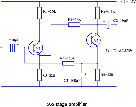
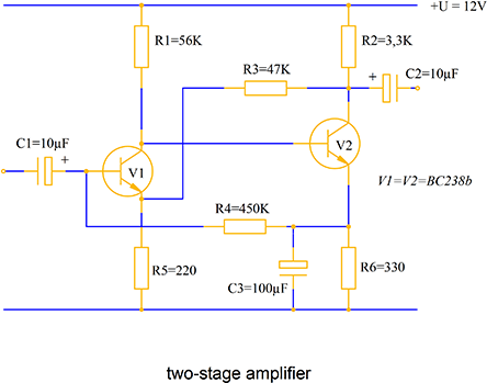
BasicsA circuit diagram consists largely of repetitive elements (yellow parts of figure 1) which, when they have been draw once, can be used again in other drawings.
Figure 1
In order to make these elements as widely usable as possible, they should be drawn in accordance with recognized standards. For example, there is a DIN Standard for the background grid behind the drawing elements. In this example the size of the background grid should be set to M=2 mm. To create universally usable elements on this grid junctions should always lie at 2M (i.e. 4 mm).
PreparationsBefore beginning drawing, turn on the display grid using the F3 key or the button in the Panel. Select 4 mm grid size so that only every other grid point, that is the points to which the crosshair snaps are displayed. The grid size can be set in the dialog called with Coordinates > Coordinate Systems > Edit - "Display Grid" or by clicking the right mouse button on the corresponding button in the Panel. Choosing 2M as the grid spacing has the advantage that screen redraws are quicker and you can also see exactly which points the connections between components lie on. In addition, turn on the position grid by pressing F4 or clicking on the button in the Panel. The position grid size should be set to 2 mm. The position grid settings can be specified in a dialog called with Manage > Coordinate Systems > Edit - "Position Grid" or by clicking the right mouse button on the corresponding button in the Panel.
Begin by creating a new library. Choose Library > Manage Libraries to call a dialog. Click on the "New" button and enter Electro.mkl into the "Library Name" field. After closing the dialog by clicking on "OK", enter Electronics Library as a description for the library. This title will be used later in the list of libraries. Next, find the new library in the list of libraries. It will still be prefixed by an 'N' to remind you that this is a new library whose contents are determined after leaving the dialog. Leave the dialog by clicking on "OK". The new library has been created, but it is still empty.
Choose a suitable zoom level (one which gives a good view of each component) to work on the components. For example, try a zoom factor of 4.
Our simple circuit diagram contains four basic library elements: resistors, capacitors, transistors and contact points. Start with the simplest component.
Resistor
Figure 2
The resistor consists of a rectangle and two short lines. Take the dimensions from the diagram. You do not need to use snapping as the position grid is active. The crosshair can only be moved in 2 mm increments. Every grid point displayed on screen is 4 mm from the next grid point because the display grid is set to 4 mm.
Once you have drawn the resistor with three objects, read it in to the library using Library > Block > Generate (Insertion Point). To do this, identify all the objects and click on the contact point at E as the insertion point. Choose the new "Electronics Library" in the Path section of the dialog which appears. Enter Resistor as the component name and leave the dialog by clicking on "OK". You have now added the first component to the library.
Capacitor
Figure 3
The capacitor is also relatively easily drawn from three lines and a rectangle. Be careful to ensure that all the connectors lie on grid points. Use the same procedure to read the capacitor into the library as for the resistor. The name of that block should be Capacitor.
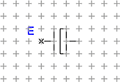
Transistor
Figure 4
Begin by drawing the connections. The line with the arrow is drawn using Annotate > Dimension Line > Straight Make sure that the "Not rotated" setting in the dimension line parameter dialog (accessible via SHIFT+SCR) is enabled or the arrow will be pointing in the wrong direction. Finally, draw the surrounding circle using Draw > Circle > Center - Point on Circle. The center of the circle is the display grid point marked with an M (Figure 4).
The radius of the circle is the point of the arrow just drawn. Choose connector E as the insertion point and read the component into the Library using the same procedure as for the resistor. To avoid confusion with other transistors which might be added to the Library later, give this transistor the name NPN-Transistor.
Contact points
Figure 5
The contact point is a circle with a 0.5 mm radius circle. Draw it on top of a grid point using Draw > Circle > Center - Point on Circle and use the direct entry method (F8) to enter the radius 0.5 mm. Read this object into the Library with the name Open Contact Point.
Next alter the circle's properties with Modify > Object Properties > Edit to solid fill (Figure 6).
Figure 6
Save this object as Closed Contact Point. The insertion point should be in the center of the circle.
CircuitAll the required components are now stored in the library. Before you draw further, make sure the blocks are saved. Do this with Library > Manage Libraries. Select the file to be saved, "Electronics Library", from the dialog and click on the "Save" button. An 'S' now appears in front of the library name. Leave the dialog by clicking on OK. The library is saved when leaving the dialog.
Use the command File > New Drawing to start drawing the circuit diagram. Activate the position and display grids with the same values used when drawing the components (2 mm position grid and 4 mm display grid). Use Manage > Pages > Edit to choose A4 landscape format and choose a zoom factor of 2 with Manage > Zoom > Factor.
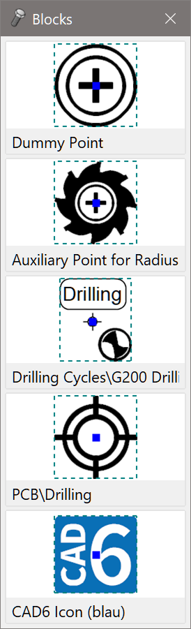
Even though not strictly needed as the diagram is not very complicated, the use of the block window is introduced at this point. Choose Window > Block Window on/off. The block window will now appear on the right of your screen. Frequently used blocks can be stored here. They can be activated by clicking on them in the block window in a similar way to choosing a command from the toolbox window.
To place a block into the block window, click the right mouse button on one of the buttons in the block window. This calls a dialog which is the same as the one called with Library > Block > Insert. Choose the library which you wish to use. Then click on the block name and choose a rotation angle and enlargement factor. As the components in the library just created are already the right size, only the rotation angle needs altering. Begin by choosing the transistor; leave the dialog by clicking on OK without altering the rotation angle. The NPN transistor should now appear in one of the block window buttons. Proceed in the same way for the other components. Add the resistor again, but rotated by 90°. If the blocks' rotation angles are not displayed, right-click the window and choose the respective option in the appearing menu.
Start by positioning the more complicated blocks. In this diagram this means the transistors. First, position transistor V1. Click on the transistor icon in the block window. The component "hangs" from the crosshair. The insertion point lies at the center of the crosshair. If the grid is active, this guarantees that the block will be inserted with its end on a grid point. Insert the element by clicking the left mouse button.
Next choose the vertical version of the resistor and place it twice on the page aligned with the upper and lower connectors of the transistor (resistors R1 and R5). You only need to position them approximately as they can easily be moved using Modify > Move Objects > Offset If the grid is on, the movement is restricted so that the components always jump to the grid points and there is no need to use the snapping functions. Use the same method to position capacitor C1.
Insert transistor V2 at its approximate position. The insertion point should be a little higher than the upper connector of V1 and enough space should be left between the two transistors for R4 and C3. The resistors R2 and R6 are positioned in a similar way to R1 and R5. Next, place the horizontal resistors R3 and R4 into the drawing. A suitable block is already available in the block window.
The capacitors C3 and C2 are rotated by 90° and 180° respectively and therefore are not in the block window. Choose Library > Block > Insert and choose the "Electronic Library" as the path. Click on the "Capacitor" block and choose 90° as the rotation angle. Close the dialog with "OK". The block is now available. Insert it into the diagram and carry out the same procedure for the second capacitor (180° rotation) (Figure 7).
Figure 7
Use Draw > Line > Polyline / Curve to draw connecting lines with 90° corners, for example between V1 and R3, on the grid. The other, short, connection lines can be added using Draw > Line > Point - Point.
Figure 8
Remember that a polyline is actually a curve on which some operations can not be carried out. To manipulate the polyline, it must sometimes be converted to a series of individual lines with Trim > Trim Object > Resolve Completely.
Next, place the block "Closed contact point" on the junctions. Place an "Open contact point" on the free ends of the capacitors C1 and C2. Finally, use Annotate > Text > Standard. to label the components. In the example, 4 mm high Times New Roman is used.
To enter a special character into the text, you can either hold down the ALT key and type the ANSI code for the relevant character on the numeric keypad and then release the ALT key, or start the Windows Character Map accessory, choose the character required, copy it to the Clipboard and then paste it into the Malz++Kassner CAD6 text field by using CTRL+V (or SHIFT+INS). This is how you add the µ symbol to the labels for the capacitors.
Figure 9
To conclude this example, the working of libraries with respect to changes is explained again. Before carrying out the further exercises, save the drawing with the name Circuit.mkd using File > Save Drawing as.
UpdatingOne advantage when libraries are used is the easy maintenance of drawings. If the block is changed after the creation of a library, then all occurrences of that block in all drawings are updated as well. Test this by using the library which you created for the circuit diagram. Make a copy of the library with the name Electronics Library Copy by using the command Library > Manage Libraries - "Save As". Later you will be able to copy the new library back to the original, undoing the changes. Before starting the exercises, start a new drawing by choosing File > New Drawing.
There are two main methods of placing new or altered blocks which will replace blocks in existing drawings into a library.
Method 1The altered block is saved under a new, different name. This method makes it possible to only alter those blocks which you really want to change. It is the safest method and should therefore be used most of the time. Its disadvantage is that a relatively high amount of effort is required, because each block must be altered in each drawing.
In the example, if the standard for depicting a transistor changes, it would be necessary to make a corresponding alteration in the library. The new representation is different from the old one in that the circle around the block is no longer used. To change the representation, place the "Transistor" block on the page and use Library > Block > Resolve Block Instances to break it into objects. Remove the circle using Modify > Delete Objects (or the DELETE key). Read the altered block back into the "Electronic Library" using Library > Block > Create (Insertion Point). If you did not have the grid active, activate "Corner/Endpoint" snapping mode to put the insertion point at the left-hand connector. Give the block the name NPN Transistor (New) to distinguish it from the old one. Save the altered version of the library by choosing Library > Manage Libraries and choosing "Save" in the dialog.
Load your drawing Circuit.mkd. Using the command Library > Replace Block you can specify which block in the loaded drawing should be replaced by the new block. Choose the blocks by clicking on "Choose" and then selecting the blocks in the library dialog. All blocks with the old name will automatically be replaced by the new block. This operation can be restricted to permanently selected objects by activating the "Selection Only" check box.
Method 2The second method is to directly overwrite the old block with the new one. This has the risk that blocks which you did not mean to alter will be altered. One advantage is that when the drawing is opened, it will already have been altered automatically.
The procedure is similar to the first method, except that the altered block is saved under the same name as the old one; it is not saved separately. After loading the drawing, you will see that the substitution has already been made.
TransformingRemove the "Electronics Library" from memory by choosing Library > Manage Libraries and clicking on the "Remove" button then leaving the dialog by clicking on "OK". The block name and library name for each block will be displayed on screen because the application cannot call on the library any more. Without the library, the circuit diagram cannot be displayed or printed properly, because the drawing only holds references to the original blocks in the library. After loading the library (with Library > Manage Libraries - "Open") the blocks will be displayed again.
To make the drawing library-independent, either transform all the external to internal blocks with the command Library > Transform External Block to Internal or making the blocks into objects again using Library > Block > Resolve Block Instances.
Transforming external blocks to internal has the advantage that all the instances are kept intact and the blocks are saved with the drawing. Change the external blocks to internal and remove the library from memory. As expected, the drawing retains its original appearance. After saving the drawing, the blocks are contained, independent of the library, in the drawing.
AttributesEach block can have unique properties (also known as Attributes). The block properties can be the same for all components or be different from component to component. Malz++Kassner CAD6 allows attributes to be attached to blocks and then output later in a parts list. Attributes which do not change for the same block are called Global Attributes. Individual properties, specified when a block is inserted into a drawing, are known as Local Attributes. Attributes should be set when a block is read in to a library.
|
CAD6studio Release 2026.0 - Copyright 2026 Malz++Kassner® GmbH