Coordinates (Basics)
|
|
Coordinates (Basics) |
www.CAD6.com |
|
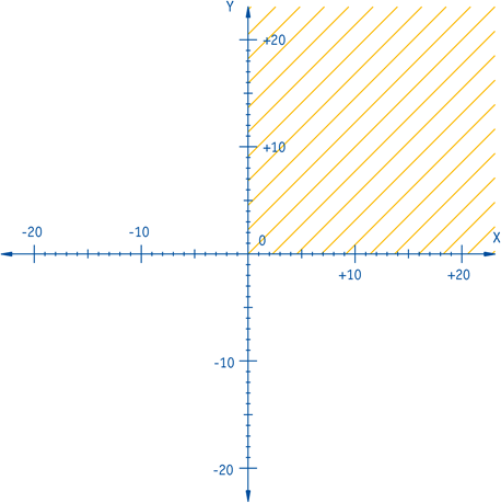
The basis for screen display is a method of describing the position of each point in your drawing. To do this, a coordinate system has to be defined. With the help of a coordinate system, each point in a drawing can be given a unique description. The best known type of coordinate system is the cartesian coordinate system. This consists of a coordinate origin and two coordinate axes at right angles to one another which meet at the origin. Usually, these axes are drawn horizontally and vertically. The horizontal axis is known as the X-axis and the vertical axis as the Y-axis (figure 1).
Figure 1: Cartesian coordinate system
Malz++Kassner CAD6 offers distorted forms of coordinate system to aid drawing in isometric and dimetric perspectives. These coordinate systems differ mainly by having a predetermined rotation angle and an altered height/width ratio. Further information on these coordinate systems can be obtained from the reference and the example on dimetric drawing.
Determination of CoordinatesFurther observations confine themselves to cartesian coordinate systems. Figure 1 shows such a coordinate system. The X-axis is numbered from left to right, and the Y-axis from bottom to top. In the standard Malz++Kassner CAD6 drawing window, the origin (that is, the point at which X and Y are 0) at the bottom left of the page. The area available to you is the area which is shaded on the graph. The origin can be moved to another point on the page which will make it possible to draw in the other areas.
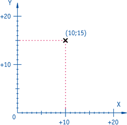
Various ways can be used to identify a point uniquely. The simplest way is the use of absolute coordinates. Absolute coordinates specify the precise X and Y values of a point (Figure 2).
Figure 2: Absolute coordinates
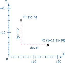
It is possible to identify a point by specifying its position relative to another point. These are called relative coordinates. The first point is treated as if it were the origin and the distance between the X and Y values of each point is given. In mathematics, this is often abbreviated as dx and dy. When (x1;y1) are the absolute coordinates of the first point and (x2;y2) are the absolute coordinates of the second point, the position of the second point relative to the first can also be described as follows: (x2;y2)=(x1+dx;y1+dy) (Figure 3).
Figure 3: Relative coordinates
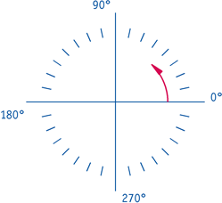
A third method is the use of polar coordinates. These coordinates are described by distance from the origin and angle from the zero-angle. The mathematical zero-angle (that is, 0°) is along the positive X-Axis, that is, at the "three o' clock" position (Figure 4).
Figure 4: Mathematical zero-angle
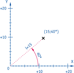
Angles are measured in an anti-clockwise direction. This form also describes the position of each point uniquely (Figure 5).
Figure 5: Polar coordinates
|
CAD6studio Release 2026.0 - Copyright 2026 Malz++Kassner® GmbH