Modify Objects (Introduction)
|
|
Modify Objects (Introduction) |
www.CAD6.com |
|
This chapter outlines the modification of already created objects. Independent of the chosen command using for modifying there are basic procedures. Already mentioned in chapter Choose Commands in CAD6, the command must be specified before the object can be selected.
Object SelectionThere are different methods of selection, which depends on the application. Find the object selection methods in the following:
While reading this chapter, CAD6 should be opened and the methods of the object selection should be reproduced. Spread a number of objects out arbitrary on the drawing area. These objects can then be selected for trials. The selection can be cancelled by right clicking or pressing the ESC key.
Selection of a single objectA single object can be selected by a left mouse click.
Selection of several objectsSeveral objects can be selected by left mouse clicks while pressing the CTRL key permanently. The selection of an object can be withdrew by a second left mouse click. By releasing the CTRL key the object selection is completed.
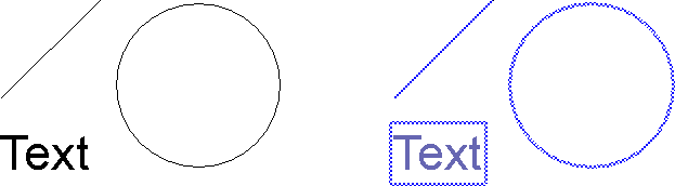
Objects before and after the Selection
Selection of objects inside a sectionA rectangular section can be selected by pressing the SHIFT key permanently. All objects inside the section will be selected provided that the objects are completely inside the section, i.e. the object must not be protruded.
Selection of objects inside a groupIndividual objects within groups can be selected by pressing the ALT key permanently. When pressing the SHIFT or CTRL key simultaneously, you can combine this with multiple object selection and selection of a section, respectively.
Selection of all objectsBy Extra > Identify > Identify All or by pressing the key "F10" all objects can be selected at the same time.
Previous identificationBy Extra > Identify > Previous Identification or by pressing the key "F11" all objects can be selected at the same time, which are identified for the previous procedure. In order to explain the manner of this command, a little example is given: A number of objects are wrapped into a block by using Library > Block > Create (Insertion Point). The objects are identified and a reference point are entered. In order to delete these objects after the creation, the command Modify > Delete Objects must be specified. By pressing the key "F11" all objects are deleted which are involved during the block creation, i.e. a new identification is unnecessary.
Clear the selection of the single objectsThe identification methods according to 3., 4., and 5. can be inverted by a left mouse click so long as the CTRL key is pressed permanently.
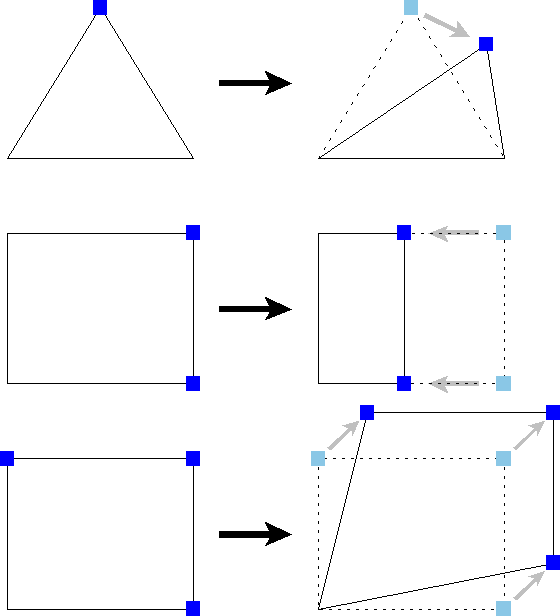
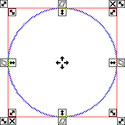
Point SelectionOne or more points can be moved by means of a point selection. This affects a compression or a dilation of the identified objects. The following figure shows the effects of the command Modify > Move Set of Points > Offset applied on the corner points (blue marked) of simple objects.
Moving points affect stretching and shorting effects
Depending on the application, CAD6 offers several commands for moving definition points:
Modify > Move Set of Points > Offset This command can be used to move several definition points related to a reference point and a target point.
Modify > Move Set of Points > Perpendicular / Parallel This command can be used to move several definition points related to the perpendicular/parallel of a specified reference object.
Modify > Move Set of Points > Relative Values This command can be used to move several definition points determined by entering a numeric value.
Modify > Move Set of Points > Single Point This command can be used to move individual object definition points. Using this function objects which cannot be manipulated with the "normal" manipulation commands (e.g. Move and Rotate) can be manipulated.
Permanent SelectionObjects can also identified permanently, i.e. the identification remains so long as it is cleared explicitly.
A permanent selection is set by Extra > Permanent Selection > Set. The selection of several objects is cleared by Extra > Permanent Selection > Clear. In connection with "Identify All" (key "F10") the identification of all permanent selected objects can be cleared. By using Extra > Permanent Selection > Invert the selection can be transferred into the opposite selection state.
Permanent selection has two uses: Firstly, a group of objects can be marked by the permanent selection. It can then be used later as the basis for normal object selection. This can be done by Extra > Use Permanent Selection or by pressing the key "F12".
Secondly, this kind of selection can be used in connection with drawing settings (Manage > Drawing Settings > Screen). There are settings which can be applied to all objects or to permanent selected objects.
Thirdly the selected group of objects can be used as an additional object selection alongside the normal, directly selected objects. This is the case with the command Move / Copy Objects > Multiple Copy, Markings.
Selection FilterIn very large drawings with a lot of different and abutting objects it can be very difficult to identify several objects. But if these objects has got the same properties or the same type, it is possible to identify the objects on the basis of their commonness by using the selection filter. A little example explains the purpose:
Initial situation: You received a drawing from a colleague that you should revise. The drawing has about 10,000 objects, each object type was used and details can only be seen in large zoom levels. You notice that an incorrect line pattern and object color has been used for a certain line type. This line type occurs around 150 times in different places.
One option, albeit a very tedious one, would be to select each of these lines individually to change the characteristics. However, you will find that this form of selection is very impractical and uncomfortable. An ideal solution in this case would be to be able to select all objects of this characteristic type with one keystroke.
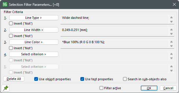
This can be realized by the selection filter. The selection can be filtered by the properties of the objects. By Extra > Selection Filter Parameters the parameter of the filter can be adjusted.
The figure above shows the needed setting for the mentioned example. Provided that the selection filter is set (Extra > Selection Filter) only the lines are selected which have the pattern type "Wide dashed line", the line width "0.25 mm", and the line color "blue".
For example if you want to change the object properties to "Dot-dash line", line width "1.0 mm" and line color "red", you have to adjust these settings in the dialog Modify > Object Properties > Edit. The command Extra > Identify > Identify All is limited to the filtered objects. Do not forget to inactivate the selection filter for following operations.
Edit PropertiesEach object has an own property set consisting of among other things line width, line pattern, line color, fill color, and fill mode. These properties determine the appearance of the objects on the screen well as on the output. The property set is established by an object creation and can be modified continuously.
In the following the term property is enhanced to direct property and indirect property. An object has got direct properties. In certain circumstances these properties can be overlaid by indirect properties. To simplify matters in a first step only the direct properties are explained by examples.
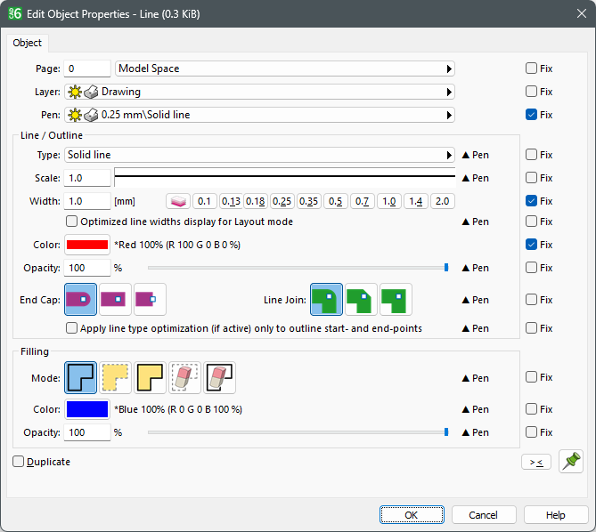
First, a line is drawn by Draw > Line > Point - Point. Second, the command Modify > Object Properties > Edit is chosen. If the line is selected, the following dialog appears:
The first three properties "Page", "Layer", and "Pen" can be ignored in a first step. The other properties affects the appearance of the object directly. In order to modify the line color or fill color the respective colored button is clicked. The modification of the color can be handled in a second dialog. Closing the dialog with "OK", all settings will be applied to the object.
Each property has a "Fix"-Flag. If this Flag is set, an overlay is blocked by the respective object property. In this example, the pen, the line color, and the line width are modified.
A further method to modify the appearance of an object is the overlay of indirect properties. This way is much complicated. If you comprehend this method the property handling is more flexible and more efficient. Indirect properties can be applied to an object in two different ways:
LayersIn addition to the property set, an objects has a reference to a layer. A layer has got the same property set as each other object. The properties of an object are not only determined by its property set but also by the transmitted properties of the layer. The properties of a layer do not alter the properties of an object but the object properties are overlaid. This means that altering the layer properties changes the appearance of the objects.
In this connection it is very important to understand that the property set of the object remains unchanged. The technical terminology for this connection is property transmission. In order not to transmit the properties of the layer the objects can refused the transmission by marking the several "Fix"-flags of Shade > Object Properties > Edit.
Screen Properties and Output PropertiesA layer consists of two property sets, one for the screen and another for the output (e.g. printer). Both can be applied to an object, therefore the appearance of an object can be different on each medium. For example if you have a colored screen but only a black and white plotter it would make sense to use two different property sets.
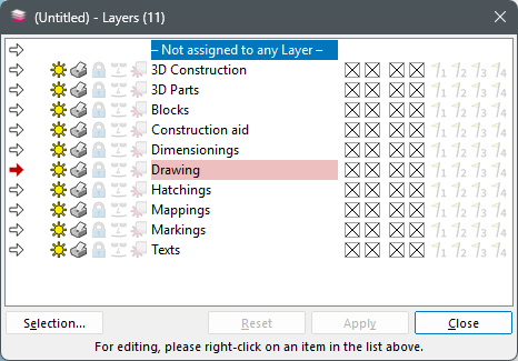
Edit LayersThe dialog Manage > Layers > Edit has a list of predefined and user-defined layers.
If a layer name is selected, the description field of the dialog shows the properties which are transferred to all objects of this layer provided that the transferring is not blocks by the object.
Display/Output of the LayerIn order to turn on/off the layers the check boxes "Display" and "Output" must be marked/unmarked. The markings apply for the currently selected layer. For a better overview two symbols show if a layer will be displayed/output. The symbol "sun" shows if a layer will be displayed on the screen and the symbol "printer" shows if the layer will be output.
Define a new layerA new layer can be defined by clicking on "New". A dialog appears in which the name of the new layer is entered. In order to create a subfolder edit "Folder\", e.g. "New Folder\New Layer".
Property Set of the LayerBy clicking the button "Screen/Output" the dialog "Edit Screen/Output Properties" appears in which the properties can be edited. A property is only transmitted if the "Transmit"-flag is specified.
To optimize the overview the screen properties can be equated with the output properties. Therefore the check box "Properties for Screen and Output Identical" must be marked and the properties to be retained must be chosen.
All changes of the settings are applied by pressing "Activate" or "Close".
PensThe handling of the pens are akin to the layers. A pen has a display and output property set as well. It is important to distinguish that a pen does not transmit any properties. A object takes on the properties of the pen provided that the transferring is not blocks by the object.
The pen settings can be adjusted by Manage > Pens > Edit analogically to the layer settings. A pen cannot transmit its properties. A object assimilates the properties from the pen. Therefore no "Transmit"-flags are needed
PagesBy assigning objects to specific pages, they will only be visible and printed if the assigned page is currently active. This can e.g. be used to handle different, overlapping drawing frames.
Modify ObjectsThe previous chapter outlines how to modify the properties of an object, such as color, pattern etc. The geometrical characteristics of an objects can also be modified, such as size, position etc. This chapter explicates the standard methods using for modifying geometrical characteristics. Please note that the command must be specified before you can identify objects.
Find most commands in the menu Modify > Objects:
...Delete This command can be used to delete selected objects and instances from the drawing.
...Modify This command can be used to modify objects and instances directly with the mouse. All basic operations like moving, scaling, rotation and distortion are available. By clicking the symbols on the edge of the object marking, respective commands can be executed. The user get a preview of all operations. By clicking the right mouse button or pressing the ESC key the command will be cancelled.
...Move / Copy > ... This command can be used to move or copy objects and instances in the drawing. All objects are copied by activating the duplicate function. Extra interesting is the movement that is specified numerically by the "Move/Copy" command "Relative Values".
...Scale >... This command can be used to scale objects and instances in the drawing (i.e. change their size).
...Rotate >... This command can be used to rotate objects and instances in the drawing.
...Mirror >... This command can be used to mirror objects and instances in the drawing. Among other things the mirroring can be managed at a straight line.
...Distort >... This command can be used to distort objects and instances in the drawing.
...Align >... This command can be used to align or center objects and instances related to the page, to a rectangular frame, or a straight line. For centering, all chosen objects and instances are treated as a single unit, that is they are all moved by the same amount. For aligning, each chosen object and instance is treated separately, i.e. is moved by an individual amount.
|
CAD6studio Release 2026.0 - Copyright 2026 Malz++Kassner® GmbH