Draw Objects (Introduction)
|
|
Draw Objects (Introduction) |
www.CAD6.com |
|
This chapter explains methods of CAD6 for drawing objects and in addition it points at typically posed problems and the corresponding solutions of Malz++Kassner CAD6.
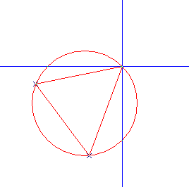
Enter Points via Mouse ControlThe simplest way to position an object on the drawing area is to use the mouse. A sample: The command Draw > Circle > Circumcircle expects the entry of three points. The selected command as well as the expected entry is indicated in the status window.
At each case the points can be positioned successively by a left mouse click. The current cursor position is displayed in the status window. Commands with several entries shows a preview with the dimension of the object corresponding to the current cursor position. In order to reverse the previous entry the ESC-key can be used to retry the entry. Clicking the right mouse button canceled the command completely.
Enter Points via Mouse Control
Mouse operations can be handled easily but do not allow exact entries without any auxiliary options. For example if you would try to draw the circle illustrated above accurate to a millimeter (without the auxiliary functions snapping and grid) it becomes apparent that the mere mouse control can only be used for improper operations. The following chapters show solutions for this problem.
Snap PointsWhat is snapping? In order to explain the purpose of snapping, a little example is given: Draw two lines by using Draw > Line > Point - Point. The end point of the first line should be equal to the start point of the second one.
You will see, that it is impossible to click the same point. Even when it looks like, a higher zoom level will show that the points are not identical. What we need is a method to tell the program that the next entry should be the end point of the first line, even if it is impossible to click the same point. This method is called Snapping.
Definition: Snapping is a method to detect exactly a certain point of a object, although the mouse click is merely around. Which points are detected is determined previously by user.
Crosshairs
The so-called crosshairs determine the snap radius. Inside of this radius points of an object are sought and are snapped, if available.
Snap ModesThe snap modes determines which kind of points are snapped by the program. The modes can be specified in the Extra > Snap Modes submenu, by the panel, or by means of the keys 1 through 9. If a snap mode is set, its panel symbol appears colored, otherwise normal (see below).
Snap Mode "Midpoint": This snap mode uses center points as snapping references. These can be the midpoints of lines or the center points of circles, circle parts, ellipses and ellipse parts. If snapping and this snap modes are active, instead of entering a point, a (partial) object is identified whose center point is then worked out.
Snap Mode "Corner/Endpoint": This snap mode can be used to insert snapping reference points at the corners and ends of objects. These are the end points of lines, curves, circular and ellipse arcs, dimension lines and hatching lines, as well as corner points within curves, surfaces, circular sectors, circular segments, ellipse sectors and ellipse segments.
Snap Mode "Intersection": This snap mode can be used to place snapping reference points at intersections within objects, with the Construction Aid and (if present) reference objects.
Snap Mode "Quadrant": This snap mode enables quadrant points to be used as snapping references. With circles and circle parts these are the points on the circle which lie at angles of 0°, 90°, 180° and 270° relative to the circle's center. With ellipses, they lie at the four ends of the positive and negative half axes. If snapping is on and this snap mode is active, instead of entering a point, a (partial) object is identified whose quadrant points are then worked out.
Snap Mode "Edge": With this snap mode points can be placed exactly on the edge of an object. If snapping and this snap mode are active, instead of entering a point, a (partial) object is identified on whose edge a point is placed.
Snap Mode "Other Point": Snapping reference points can be placed at other points using this command. "Other Points" are all definition points which cannot have snapping reference points placed on them with other snap modes, for example the pivot points of Bézier curves, end points of ellipse's half axes, position points of dimensions, the corners of multiple line text frames, etc.
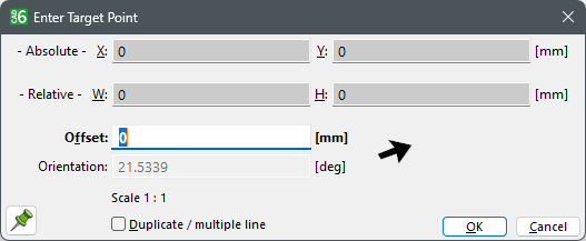
Snap Mode "Relative": Snapping reference points can be placed at a specific offset to a given point. After entering the reference point (either directly or using another snapping mode), entry fields appear in the status line, allowing to enter the offset.
This message appears if no point could be snapped inside the crosshair radius.
This message appears if a point could be snapped successfully. In this special case, a point at the corner or end of an object was snapped.
Be aware which snap mode is currently active and which kind of point are you going to snap! For example, if you want to snap the intersection of two lines and the snap modes "Intersection" and "Edge" are active, the program could snap the edge of one of the lines instead the intersection. Under certain circumstances the mistake doesn’t catch the user’s eye at once. The "dangerous" snap modes are "Midpoint", "Quadrant", and "Edge".
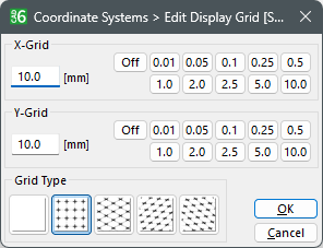
GridA further possibility to position objects is given by using the grid. The drawing area are divided in an user defined X-Grid and Y-Grid. The position entries are dragged on this grid, e.g. a grid of 1 inch drags all entries to a multiple of 1 inch. This method gives the warranty that all entered coordinates have not decimal places. All grid values are related to the origin.
There are two kinds of grids, the Display Grid and the Position Grid. Both grids are adjustable in the same way. The display grid is only used as an optical utility, e.g. for realizing proportions and the like. The position grid works in the manner explained above, i.e. it drags position entries on its grid. The position grid is not displayed.
In order to enable/disable the grids, use Manage > Coordinate Systems > Display Grid active / Position Grid active, respectively. If a grid is set to active, it is indicated by a check mark in the menu. Alternatively the key "F3" (Display Grid) or key "F4" (Position Grid) can be used.
In order to adjust the desired resolution of the grids, either the commands Manage > Coordinate Systems > Edit Display Grid / Edit Position Grid or a right click on the symbols of the panel opens the respective dialog. The grid type depends on the specifies coordinate system (see chapter Coordinate System, Scale, and Unit).
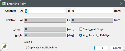
Coordinate Entry via KeyboardThe previous chapters outlines many methods for the point entry by means of auxiliary functions. A direct, numeric coordinate entry is explained in this chapter. The coordinate are entered in the status window by Extra > Coordinate Entry or by pressing key "F8".
By mouse or tabulator, the desired entry field can be edited. Pressing the ENTER key the coordinate entry is applied to the current selected object. Pressing the ESC key cancels the entry.
Construction AidA further major auxiliary function of CAD6 is the construction aid. In order to explain the purpose, here is a little geometric class example: A square and a circle are drawn on a sheet of blank paper. The both objects should have the same center point. The diameter of the circle should be equal to the side length of the square.
We can solve the problem by grooving the peak of a compasses in the midpoint of the square. The compasses width must correlate with the side length of the square. There are some possibilities to calculate the center point, e.g. you can size the side length by a ruler and mark the point at the half of the edge at each case. By joining each markings with the markings of the opposite side, the midpoint can be calculated. A further possibility to calculate the center point of the square is to calculate the intersection of the bisector of the angles. However the points are calculated, construction aids are essential.
An effective CAD System should have the same construction aid methods. Of course bisectors of angles or mid-perpendicular must not be calculated by user, but calculated by the program. All construction aid can be showed or hidden and can be saved. Everything described in the previous chapters can be applied to the construction aids, e.g. snapping, grid and the like. Find some examples in the following.
There are many methods in CAD6 working with construction aid. It is impossible to outline all methods in an introduction. This chapter gives you an idea only, how to work with construction aid objects.
Example 1Starting with the simple example from above. A square and a circle are drawn and both objects should have the same center point. The diameter of the circle should be equal to the side length of the square.
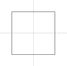
Firstly a square is drawn by Draw > Polygon > Rectangle. Due to the fact that the rectangle is a square, all edges must have the same side length. One possibility to draw this object is to position the start point in the origin and the end point with an identical X/Y coordinate. The next steps describe the methods for the determination of the center point (see above). Of course in practice only one way would be necessary.
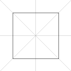
The mid-perpendicular can be drawn by Construct > Construction Aid Endless Line > Mid-Perpendicular. The program needs a reference line to carry out the command. For this sample there is both a vertical and a horizontal Mid-Perpendicular, so that the command must be used two times. Was the entry correct, the result on the display must be the same as in the following figure:
Construction Aid Mid-Perpendicular
The problem is already solved but for the sake of completeness the second solution is displayed. The bisector of the angles between two reference lines are drawn by Construct > Construction Aid Endless Line > Angle Bisector.
Construction Aid Bisector
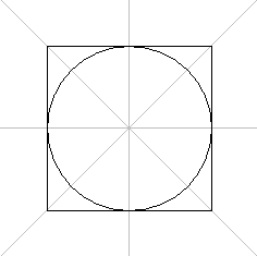
Now it is very easy to position the circle in the middle of the square. The snapping modes "Construction Aid", "Intersection", and "Edge/Endpoint" must be activated. The circle is drawn by Draw > Circle > Center - Point on Circle. The center point is the snapped intersection of the construction aid. The intersection of the mid-perpendicular and the square is the exact diameter of the circle. Was the entry correct, the result on the display must be the same as in the following figure:
Snapping of Construction Aid Objects
By pressing the key "F9" the construction aid objects can be enabled/disabled.
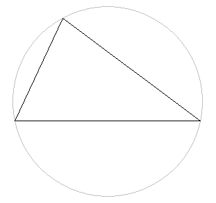
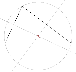
Example 2The second example shows an application with the construction aid object circle. The midpoint of a circumference should be calculated. This is the center point of the circle which runs through the corner of the triangle (so-called circumference).
Working with Construction Aid
The circumference is drawn by Construct > Construction Aid Circle > Circumcircle. The three required points are the corner points of the triangle. The snap mode "Construction Aid" and "Corner/Endpoint" should be activated.
Construction Aid Circular Arc
Finally the center point of the circle must be calculated and marked by Construct > Marking > Single. The snap mode "Construction Aid" and "Midpoint" should be activated. The result can be audited by drawing the perpendiculars of the triangle (see example 1).
Construction Aid Marking
Using DigitizersWorking with CAD6 can be made a lot easier by using a digitizer (also known as a "graphics tablet" or simply a "tablet"). A digitizer allows faster and more accurate input than a conventional mouse and the digitizer's large input area can also be used to select commands.
For further information on using digitizers and required settings, please refer to the chapter Using Digitizers.
|
CAD6studio Release 2026.0 - Copyright 2026 Malz++Kassner® GmbH