Example 9: Roughing out Kidney using Milling Cycles (CAM Introduction)
|
|
Example 9: Roughing out Kidney using Milling Cycles (CAM Introduction) |
www.CAD6.com |
|
Sample Drawing: "CAM\Roughing out Kidney using Milling Cycles"
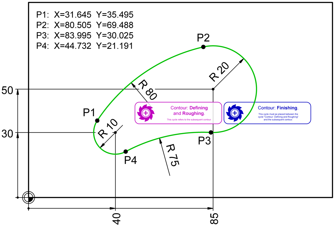
Export ObjectsThe surface to be roughed out and finished is shown in green in the drawing. The associated NC blocks (lines) also appear in this color.
The points P1 to P4 only serve to represent the tangential circular arc transitions. For the construction of the kidney with the commands Construction Aid Circle > Center - Point on Circle, Construction Aid Circle > Radius - Object - Object and then Construction Aid > Contour Tracking Surface, the dimensions for the circle radii and centers are sufficient.
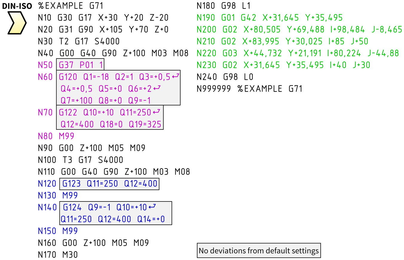
The CAM block instance "Cycles\Contour: 1. Defining and Roughing" comes before the CAM block instance "Cycles\Contour: 2. Finishing (Floor and Side)". in the object order. The associated NC records (lines) are highlighted in color. The position of these CAM block instances on the artboard does not affect the NC code.
The only important thing is that the contour to be cleared out and finished follows directly on the CAM block instances!
Of course, you can also clear and finish several surfaces in one export process. The contour subprograms, each with their own number, are always at the end of the NC file. In this case, please make sure to deactivate the "Sort Export" option in the dialog window of the CAM > Manage Tool List command, otherwise the postprocessor will not correctly recognize the additional contours!
Milling Cycles for Outline Sub-ProgramsThe G commands framed in the NC code and their parameters ensure that subprogram 1 is defined as a contour with additional data (G37/G120), then cleared out (G122) and finally finished (G123/G124). These G commands originate from the two CAM block instances mentioned above. These G commands are special cycles of the Heidenhain control (e.g. TNC 426), so-called SL cycles group II. These cycles make it possible to apply very complex work processes to the specified contour subprograms. All tool positioning is carried out independently by the control based on the defined contour and the additional data.
The necessary parameters, such as infeed depths, finishing dimensions and feeds come from the respective tool. Of course, all milling cycles could also be in one CAM block instance. How you design the allocation of the milling cycles to CAM block instances should be based on your operational practice.
Whether you prefer powerful CAM block instances, each with as many milling cycles as possible, or flexible CAM block instances with as few milling cycles as possible, we are happy to help you with the customization!
|
CAD6industrie CAM Release 2026.0 - Copyright 2026 Malz++Kassner® GmbH