Example 8: Merge Contour with Milling Cycles (CAM Introduction)
|
|
Example 8: Merge Contour with Milling Cycles (CAM Introduction) |
www.CAD6.com |
|
Sample Drawing: "CAM\Merge Contour with Milling Cycles"
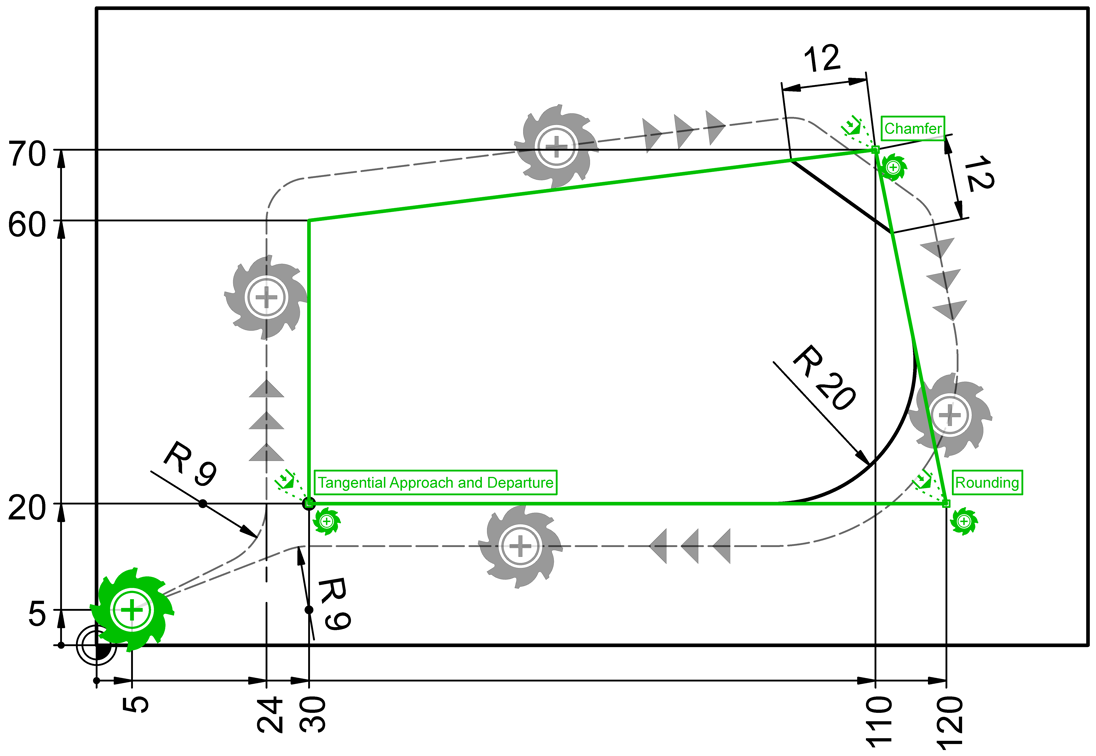
Export ObjectsThe objects to be exported are shown in green in the drawing. The associated NC blocks (lines) also appear in this color.
The block instance "Auxiliary Point for Radius Compensation" comes from the "CAM Universal" library and is located at position (5|5).
It is important for the correct export that this CAM block instance is in the order before the actual milling contour!
The three milling cycles are the block instances "Milling Cycles\G26/G27 Tangential Approach and Departure", "Milling Cycles\G24 Inserting Chamfer" and "Milling Cycles\G25 Rounding Corner" from the "CAM Universal" library. These milling cycles must also be in sequence before the milling contour and they must each be positioned exactly on a point on the milling contour.
The milling contour to be exported consists of a square, with the starting point of the square being at position (30|20). The direction of the square is clockwise, which means the next point is at (30|60). However, due to the milling cycles "G24 Inserting Chamfer" and "G25 Rounding Corner" used, the actual milling contour deviates from the exported one. Since the radius correction is active in the tool list for this tool (here G41), the machine control automatically calculates the actual tool path based on the milling contour and the milling cutter radius (see dashed line). All milling cycles are taken into account here, i.e. both the chamfer and the rounding as well as the tangential approach/departure.
Merge Contour with Milling CyclesFramed in the NC code on the left are the positions where NC commands of the milling cycles have been merged with the NC commands of the milling contour. You can see that the milling cycles are always inserted after approaching the respective contour point or are in the same block (APPR LCT). The Heidenhain control (e.g. TNC 426) then calculates the tool path for tangential approach/departure so that the circular arcs (radius 9) merge tangentially into the tool path. Likewise, the Heidenhain control does not actually approach the contour corner points for the chamfer or rounding, but uses the corner points to calculate the tool path in such a way that a chamfer with a length of 12 and a rounding with a radius of 20 is created.
When inserting a CAM block instance with milling cycles (by setting the appropriate check box in the Block > Insert dialog) or afterwards (using the Shape > Edit > Text / Attributes command), you can still edit local attributes if required. For example, you can assign a different chamfer length or a different rounding radius. The values used here come from the "Extra Milling Parameters" of the tool used.
|
CAD6industrie CAM Release 2026.0 - Copyright 2026 Malz++Kassner® GmbH