Example 4: Engraving (CAM Introduction)
|
|
Example 4: Engraving (CAM Introduction) |
www.CAD6.com |
|
Sample Drawing: "CAM\Engraving"
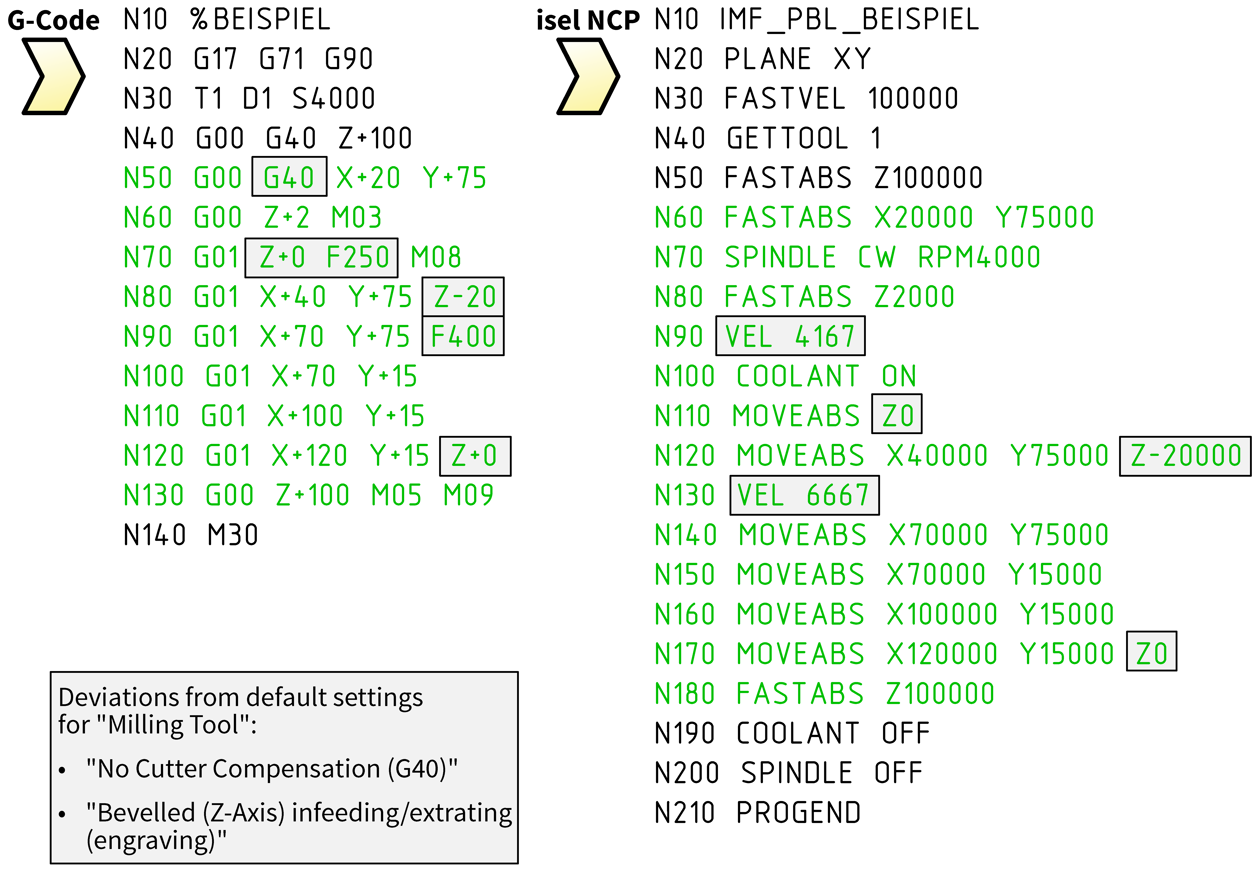
Export ObjectsThe object to be exported is shown in green in the drawing. The associated NC blocks (lines) also appear in this color.
The tool path is identical to the engraving contour. The tool path starts at position (20|75) and ends at (120|15). The radius correction is switched off (G40) and the engraving contour is not changed before the export in CAD6 either.
EngravingThe positions in the NC program describe the center line of the engraving contour, which is traversed in exactly the same way by the machine control without any changes. From the starting point (20|75) at Z depth 0, the tool moves diagonally (Z axis) to the point (40|75) at Z depth -20. From there, the tool moves via points (70|75) and (70|15) to point (100|15). From here, the tool moves diagonally (Z axis) to the end point (120|15) at Z depth 0.
The second and penultimate point of an engraving contour thus determines how long the starting and ending slope (Z-axis) is.
You can add a new point to an existing polyline using the command Trim > Surface / Curve > Edit: Bisect Element. You can then move this to any position, for example with Shape > Move Set of Point >.
Normally one would probably not engrave with the standard tool, but choose a special tool for engraving. However, this is irrelevant for this example, because it is intended to show that engraving is a special case of milling. Because when engraving, the drawn engraving contour is simply adopted as a tool path. There is no radius correction, neither automatically by the machine control nor manually using a CAM command.
|
CAD6industrie CAM Release 2026.0 - Copyright 2026 Malz++Kassner® GmbH