Example 2: Milling with Radius Compensation (Z-Increment) (CAM Introduction)
|
|
Example 2: Milling with Radius Compensation (Z-Increment) (CAM Introduction) |
www.CAD6.com |
|
Sample Drawing: "CAM\Milling with Radius Compensation"
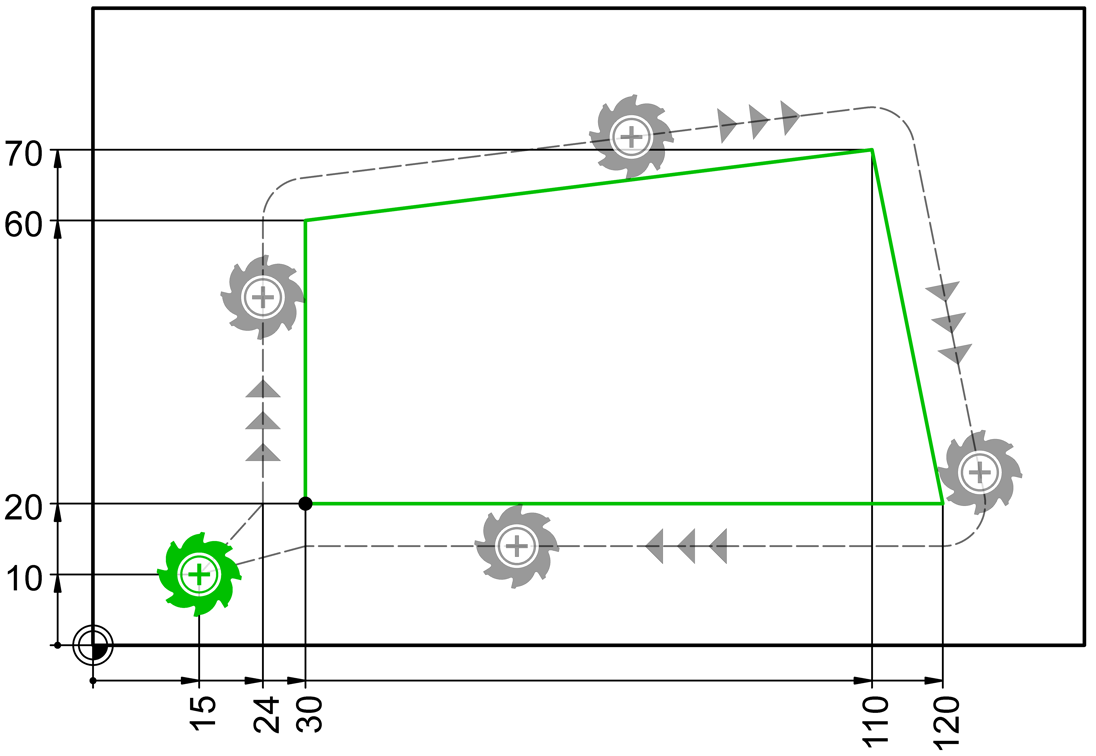
Export ObjectsThe objects to be exported are shown in green in the drawing. The associated NC blocks (lines) also appear in this color. The export objects are absolutely identical to those from the previous example, after all it is also the same example drawing. However, the number of increments of the relevant tool was set to 3.
The object at position (15|10) is the block instance "Auxiliary Point for Radius Compensation" from the "CAM Universal" library.
It is important for the correct export that this CAM block instance is in the order before the actual milling contour!
The milling contour consists of a square, with the starting point of the square being at position (30|20). The direction of the quadrangle is clockwise, which means the next point is at (30|60). Since the radius correction is active in the tool list for this tool (here G41), the machine control calculates the actual tool path based on the milling contour and the milling cutter radius (see dashed line).
Start ExportTo create the NC program shown, start the CAM > Export with Postprocessor command and then simply select the two green objects. In the preview window that appears, you can check the sequence again and then create the NC file by pressing a button.
Workpiece Zero PointThe workpiece zero point results from the current origin of the drawing. You can easily reposition it using the Manage > Coordinate Systems / Scales > Set Origin command. You specify the unit for position/length information in the NC file, for example [mm] or [µm], in the postprocessor settings.
Milling with Multiple Z IncrementsThe milling contour is traversed in three passes. Before each pass, the cutter is lowered to the required depth. For the first pass, the contour starting point (30|20) is approached from the auxiliary point (15|10) at an angle (Z axis) with activated radius compensation, left (G41). For the second and third pass, the milling cutter is lowered further at the starting point by the increment value (6.667). After the third pass, the cutter is at the start/end point of the contour (30|20) at a Z depth of 20. From there, with deactivated radius correction (G40), it moves diagonally (Z axis) back to the auxiliary point.
With the help of the commands in CAM > Display you can switch on the on-screen display of points, contour start point and direction as well as object numbers for each object. Furthermore, you will also find commands in the CAM menu to control the output sequence, change the running direction and define a new starting point.
|
CAD6industrie CAM Release 2026.0 - Copyright 2026 Malz++Kassner® GmbH