Example 12: Cutting Contour (CAM Introduction)
|
|
Example 12: Cutting Contour (CAM Introduction) |
www.CAD6.com |
|
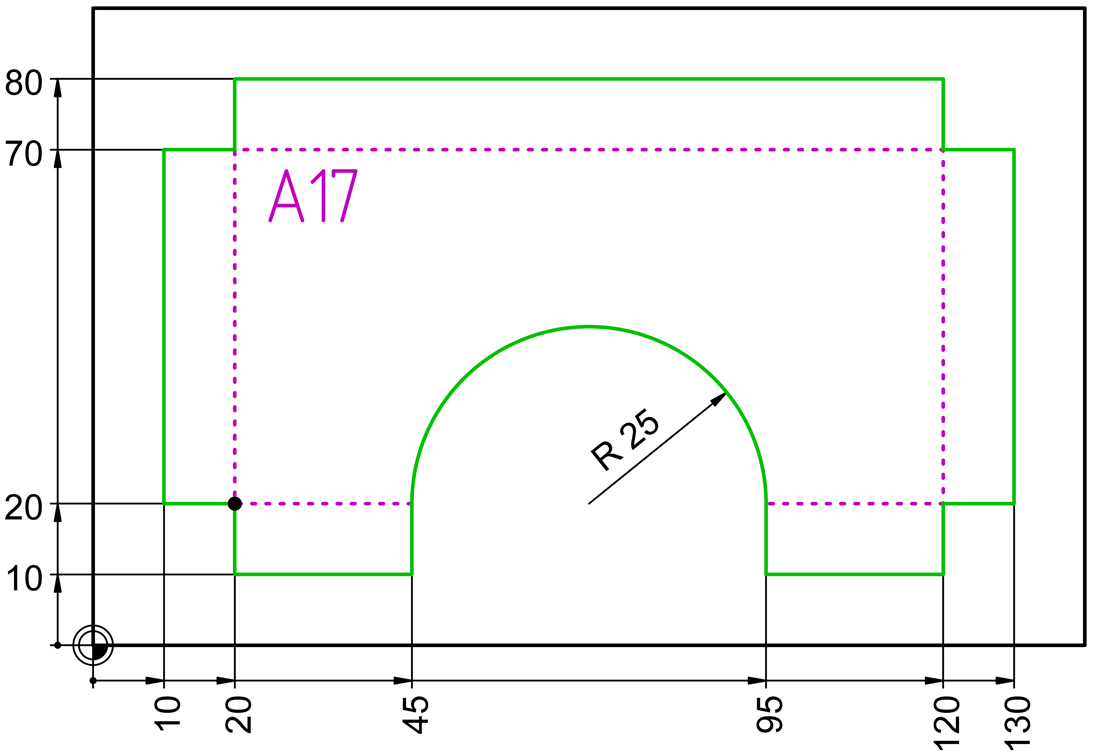
Sample Drawing: "CAM\Cutting Contour"
Export ObjectsThe contour to be cut is shown in green in the drawing. The contour has its starting point at (20|20) and the direction of rotation is clockwise. This contour belongs to the "Cutter\Cutting, film" layer, which is assigned to the logical tool "Cutter, universal" (machine tool number 1) in the tool list.
The inner (dotted) contour starting at (45|20) and the text "A17" belong to the "Cutter\Drawing with pen" layer, which is assigned to the logical tool "Pen" (machine tool number 2) in the tool list. These contours are only traced with a pen. The dotted contour is traced with a solid line because it is easier to see on the slide and it would take much longer to draw a dotted line.
The position of the logical tools in the tool list determines the order in which the contours are output. The position of the logical tool "Pen" is above the logical tool "Cutter, universal". This means that the corresponding contours are first traced and then the contour shown here in green is cut. The position of a logical tool in the tool list takes precedence over the order of objects in the drawing. This means that if a cut contour comes before all other objects in the object sequence, the objects of the logical tool "Pen" are output first. In the course of the output for a logical tool, however, the respective object order from the drawing is of course retained.
By the way, the text was created with the font "DINDRAFT" (included with CAD6). "DINDRAFT" is a one-line font that is plotted very quickly. It is therefore very well suited for the output of version numbers or comments.
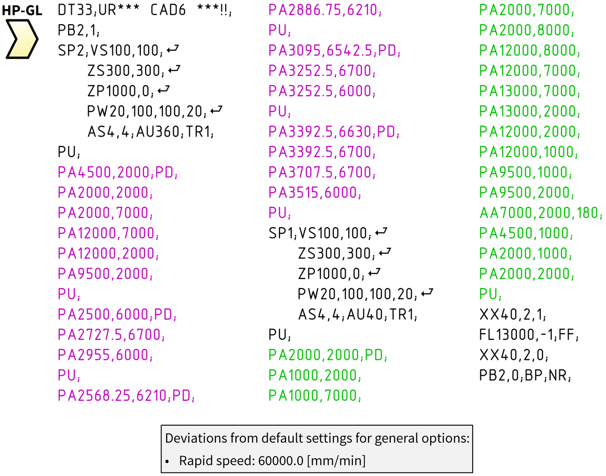
The drawing for this example was created in millimeters (scale 1:1). However, according to the HP-GL user manual for ZÜND cutting plotters, the NC code contains coordinates in 1/100mm. If necessary, the postprocessor can also be configured so that the coordinates are in millimeters.
Origin / Zero PointThe origin (0|0) of the drawing corresponds to the zero point of the cutting plotter or the reference point you entered manually. It is absolutely necessary to set the origin correctly before exporting! Otherwise the output will not be at the desired position or nothing will be output at all because the output coordinates are outside the coordinate range of your cutting plotter.
Material AdvanceIf your cutting plotter has a material transport device or a single sheet feeder, these can be controlled by the "ZÜND HP-GL" postprocessor. To do this, you can use the CAM > Edit Postprocessor command to activate "Material Advance" and define the size of the work area and the overlap. The control text for material feed also have to be adjusted. We'll be glad to help you!
|
CAD6industrie CAM Release 2026.1 - Copyright 2026 Malz++Kassner® GmbH