Example 10: Roughing out Kidney with Islands using Milling Cycles (CAM Introduction)
|
|
Example 10: Roughing out Kidney with Islands using Milling Cycles (CAM Introduction) |
www.CAD6.com |
|
Sample Drawing: "CAM\Roughing out Kidney with Islands using Milling Cycles"
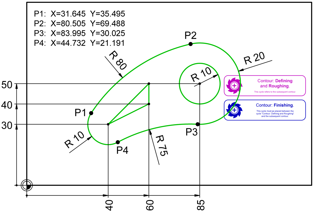
Export ObjectsThe surface to be roughed out and finished is shown in green in the drawing. The associated NC blocks (lines) also appear in this color. The outer contour is identical to the kidney from the previous example. The first inner contour is the triangle. The starting point of the triangle is at (40|30). This is followed by the point (60|50) and finally the point (60|40). So the triangle is clockwise. The second inner contour is the circle. This circle is represented by two semicircles oriented counterclockwise. The starting point of the first semicircle is at (95|50).
The CAM block instance "Cycles\Contour: 1. Defining and Roughing" comes before the CAM block instance "Cycles\Contour: 2. Finishing (Floor and Side)". in the object order. The associated NC records (lines) are highlighted in color. The position of these CAM block instances on the artboard does not affect the NC code.
The only important thing is that the contour to be cleared out and finished follows directly on the CAM block instances!
Of course, you can also clear and finish several surfaces in one export process. The contour subprograms, each with their own number, are always at the end of the NC file. In this case, please make sure to deactivate the "Sort Export" option in the dialog window of the CAM > Manage Tool List command, otherwise the postprocessor will not correctly recognize the additional contours!
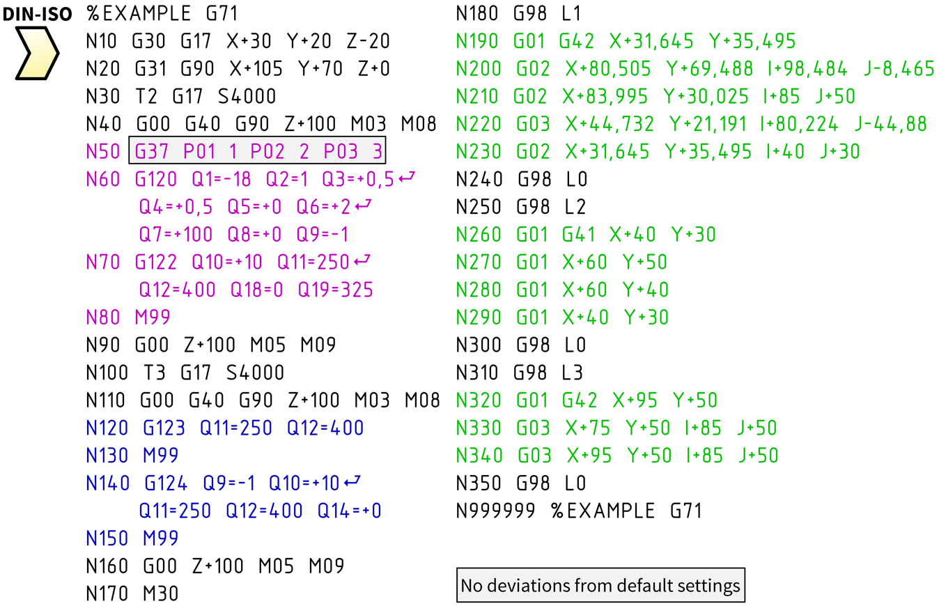
Milling Cycles for Outline Sub-ProgramsThe milling cycles in this example are identical to those in the previous example, except for the framed G command for defining (G37) the three contours (one pocket plus two islands). The outer contour (pocket), which always comes first, is also identical to that from the previous example. The following two contours for the islands are new.
After drawing the individual contours, you can use the command CAM > Output Order > Sort Objects Manually to put them in the correct order. If necessary, you can also change the starting point and the running direction of a contour with the commands CAM > Set New Contour Starting Point or CAM > Running Direction > Invert Single Object.
Then use the Trim > Surface / Curve > Combine Outlines command to make one object out of the three individual contours. This is crucial, otherwise the inner contours will not be recognized as islands. If you (temporarily) fill the area created in this way using the Shape > Object Properties > Edit command, you can more easily identify the area to be cleared. After selecting the objects for export, the postprocessor then automatically generates the appropriate contour subprograms and always places them at the end of the NC file.
The contour subprograms do not contain any commands for changing the Z-axis position. The postprocessor also does not generate any feed commands (F) or M commands in contour subprograms (the control would ignore them anyway). The current tool is selected prior to executing a milling cycle. And the parameters for the respective milling cycle (Z infeed, feed rates, etc.) are initialized by the postprocessor with the values of the currently selected tool.
|
CAD6industrie CAM Release 2026.0 - Copyright 2026 Malz++Kassner® GmbH